
S2000 L4-2.2L (2004)
Fuel Gauge Sender: Testing and Inspection
Fuel Gauge Sending Unit Test
NOTE: For the fuel gauge system circuit diagram, refer to the Gauges Circuit Diagram.
1. Check the No. 5 INSTRUMENT LIGHT BACK UP LIGHT (7.5 A) fuse in the under-dash fuse/relay box.
-
If the fuse is OK, check for an open in the YEL wire between the gauge assembly and the No. 5 INSTRUMENT LIGHT BACK UP LIGHT (
7.5 A) fuse.
-
If the fuse is blown, replace it, and check for an open in the YEL wire between the gauge assembly and the No. 5 INSTRUMENT LIGHT
BACK UP LIGHT (7.5 A) fuse.
2. Remove the rear tray.
3. Remove the access panel from the floor.
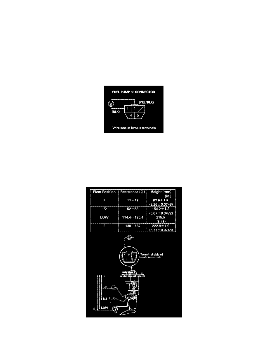
4. Disconnect the fuel pump 5P connector.
5. Measure voltage between fuel pump 5P connector terminals No. 1 and No. 2 with the ignition switch ON (II). There should be about 5 to 8 V.
-
If the voltage is as specified, go to step 6.
-
If the voltage is not as specified, check for:
-
an open or short in the YEL/BLK or BLK wire.
-
poor ground (G601).
-
a faulty main printed circuit board in the gauge assembly.
6. Turn the ignition switch OFF.
7. Remove the bolts and the fuel tank unit.
8. Measure the resistance between the No. 1 and No. 2 terminals with the float at E (EMPTY), LOW (LOW FUEL INDICATOR LIGHT IS ON),
1/2 (HALF FULL) and F (FULL) positions. If you do not get the following readings, replace the fuel gauge sending unit.