
H1 V8-65L DSL (1998) Diesel MFI Pump Reset Procedure - Page 395
A fault in either component will cause an injection pulse width.
Fuel Solenoid Driver Replacement
Removal
1. Drain the engine coolant and remove the upper radiator hose from the thermostat housing.
2. Remove the left intake manifold runner to gain access to the Fuel Solenoid Driver (on the left side of the injection pump).
3. Scribe a reference mark on the engine front cover and the injection pump housing to assist in correctly locating the Injection Pump during
reassembly.
4. Loosen the Injection Pump retaining nuts approximately 1/2 turn, using Injection Pump Timing Wrench J 41711 (do not remove the nuts).
5. Rotate the Injection Pump toward the passenger side of the vehicle until it stops, using Injection Pump Adjusting tool J-33042, and re-tighten the
top Injection Pump retaining nut.
6. Disconnect the wiring connector at the Fuel Solenoid Driver (Figure 3-16).
7. Loosen the four Fuel Solenoid Driver mounting screws until they are free of the injection pump housing, using a T 15 Torx bit.
8. Remove the mounting screws, Fuel Solenoid Driver and the heat transfer pad from the Injection Pump. Discard the heat transfer pad and the
mounting screws.
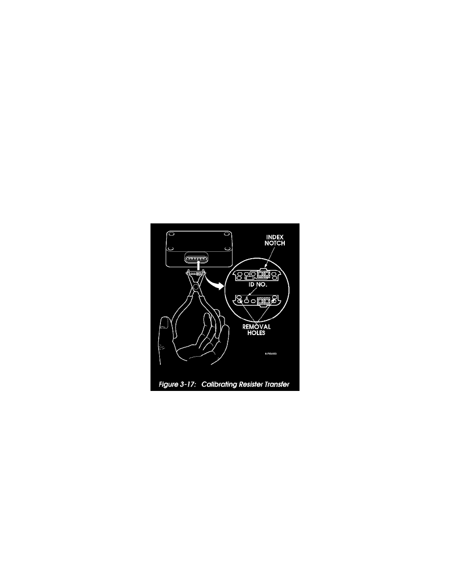
9. Remove the calibrating resistor (Figure 3-17) from the Fuel Solenoid Driver using special pliers (Klein D319B or Stanadyne 30858).
CAUTION:
-
The Calibrating Resistor is specific to the injection pump. Do not damage the resistor. The calibrating resistor identification number
is located on the front of the Calibrating Resistor (Figure 3-17).
-
If the Calibrating Resistor is damaged or lost, the Injection Pump must be removed for replacement or taken to a Stanadyne dealer
for calibration. If the Calibrating Resistor is missing a DTC P1218 will set.
Figure 3-17: Calibrating Resister Transfer
Installation
1. Install the calibrating resistor in the new Fuel Solenoid Driver using the special pliers (Figure 3-17).
2. Place the new heat transfer pad on the side of the Fuel Solenoid Driver and insert the mounting screws through the driver and the pad.
3. Align the Fuel Solenoid Driver mounting screws with the holes in the pump housing and tighten to 23 lb-in (2.75 N.m).
CAUTION:
-
Do not install the Fuel Solenoid Driver without the heat transfer pad. Do not reuse a heat transfer pad. Use a new heat transfer pad
only. The heat transfer pad is required to prevent overheating and rapid failure of the Fuel Solenoid Driver.
-
Do not overtighten the Fuel Solenoid Driver mounting screws. Damage to the Fuel Solenoid Driver will result.
4. Connect the Fuel Solenoid Driver wiring harness connector.
5. Loosen the upper Injection Pump retaining nut approximately 1/2 turn (do not remove the nut).
6. Rotate the Injection Pump back to it s original position, using the reference marks made previously and tighten the Injection Pump retaining nuts.
7. Install the intake manifold runner.
8. Connect the upper radiator hose to the thermostat housing and fill the coolant system.
9. Perform the Injection Timing Adjustment Procedure.