
V8-65L Diesel Turbo | Fuel Delivery and Air Induction
Diesel MFI Pump: Description and Operation
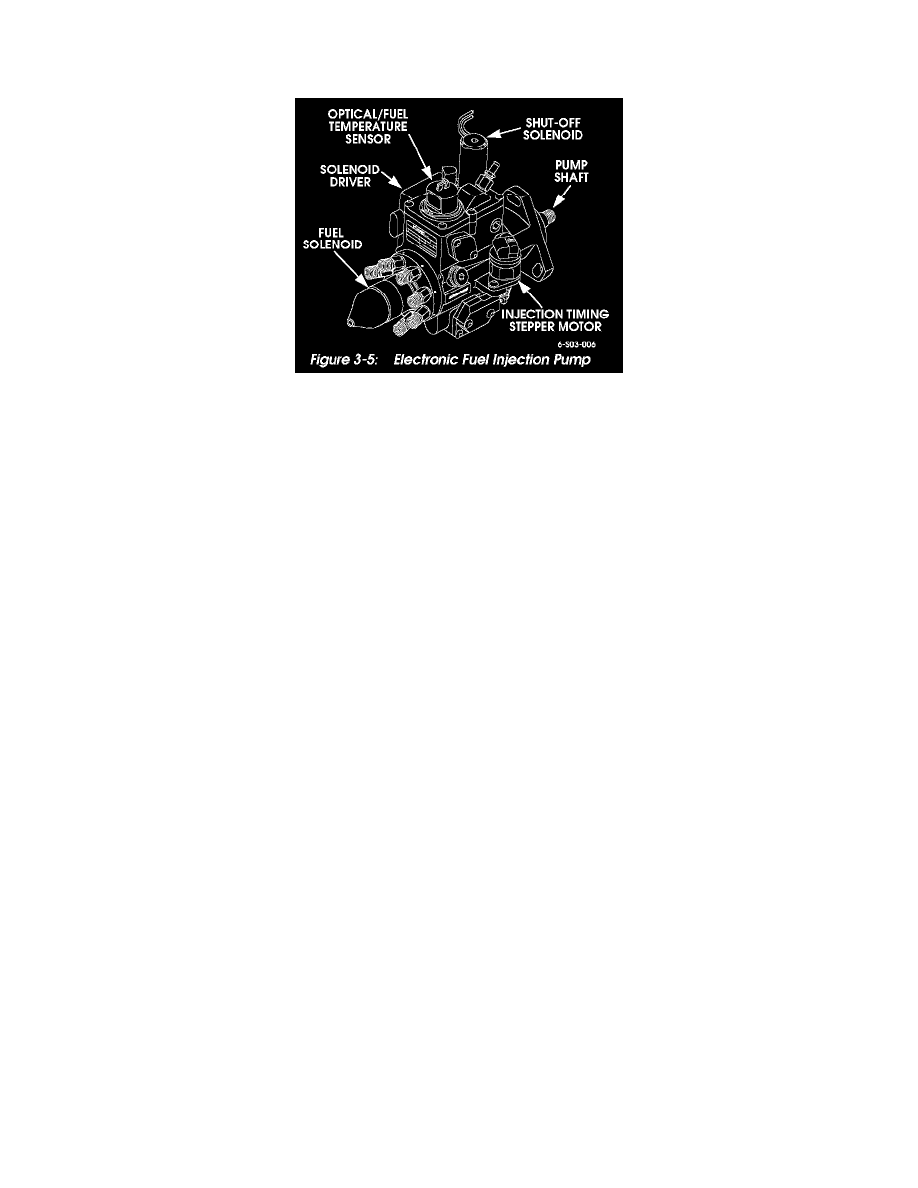
Electronic Injection Pump -- Turbo Diesel
Figure 3-5: Electronic Fuel Injection Pump
Electronic Injection Pump
The turbo diesel injection pump (Figure 3-5) is controlled by the powertrain control module based on inputs from the electronic accelerator pedal and
various engine sensors.
The drive mechanism for the pump consists of a drive gear on the camshaft, and a driven gear on the pump. The pump is operated at camshaft speed in
the opposite direction of rotation.
A rotary type pump mechanism pressurizes fuel to the injectors. Pressure at the injector nozzles is approximately 2000 psi (138 bar). Residual pressure
in the injector lines is maintained at 500 psi (3447 kPa) during operation.
Fuel distribution to individual nozzles occurs at the pump head and rotor assembly and is activated by the fuel solenoid driver. High strength, plated steel
lines are used to connect each injector to the pump.
The powertrain control module controls injection timing and fuel mixture according to input signals from various sensors.
A crankshaft position sensor and optical sensors are used to provide engine and injection pump position and speed signals. These signals are transmitted
to the PCM and used as reference for fuel flow and timing.
The injection pump is equipped with a shut off solenoid controlled by the PCM. The purpose of the solenoid, is to close and stop fuel flow within the
pump. This occurs when the ignition switch is moved to the "Off" position. At this point, loss of PCM hold-open voltage de-energizes the solenoid
causing it to close.