
H1 V8-6.5L DSL Turbo (1999)
Turbo Boost Sensor: Testing and Inspection
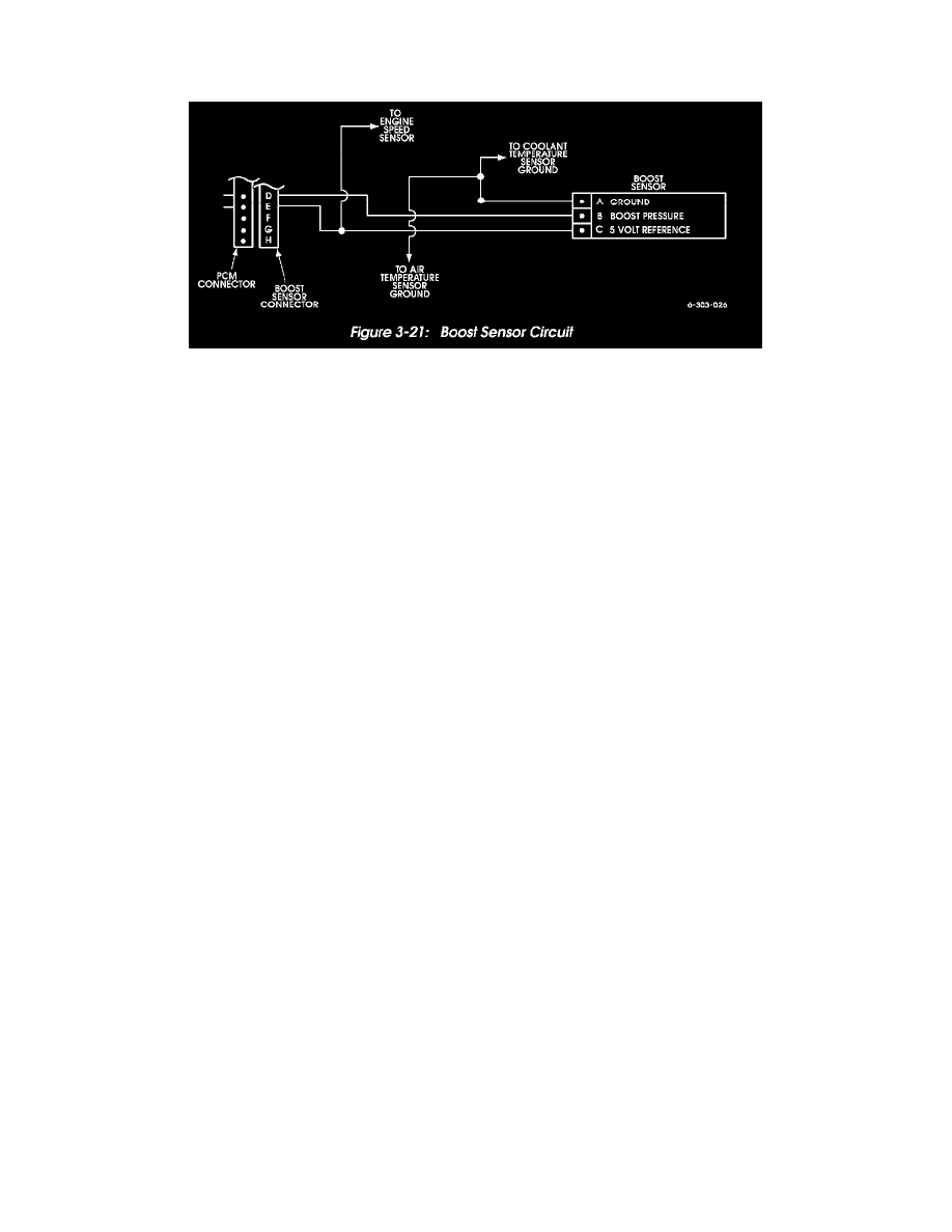
Boost Sensor Circuit Test
Figure 3-21: Boost Sensor Circuit
Boost Sensor Circuit Test
1. Connect scan tool to diagnostic/data link connector.
2. Start and run engine at idle speed.
3. Record boost sensor voltage.
-
If voltage is 4.0 volts or more, continue test.
-
If voltage is less than specified, compare sensor to known good one. Voltage should not vary by more than plus or minus 0.4 volt. If sensor
voltage compares favorably with known good sensor, problem is in wiring or connections.
4. Turn ignition off and disconnect boost sensor wires.
5. Turn ignition switch back on (engine off), and note scan tool voltage reading.
-
If boost voltage is 1 volt or less, continue test.
-
If voltage is less than specified, problem is in wiring or connections between sensor and PCM.
6. Connect 12 volt test lamp between sensor terminal C and battery positive post.
-
If lamp illuminates, problem is with sensor, connectors, or fitting.
-
If lamp does not illuminate, problem is open wire.