
H1 V8-6.5L DSL Turbo (1999)
Accelerator Pedal Position Sensor: Testing and Inspection
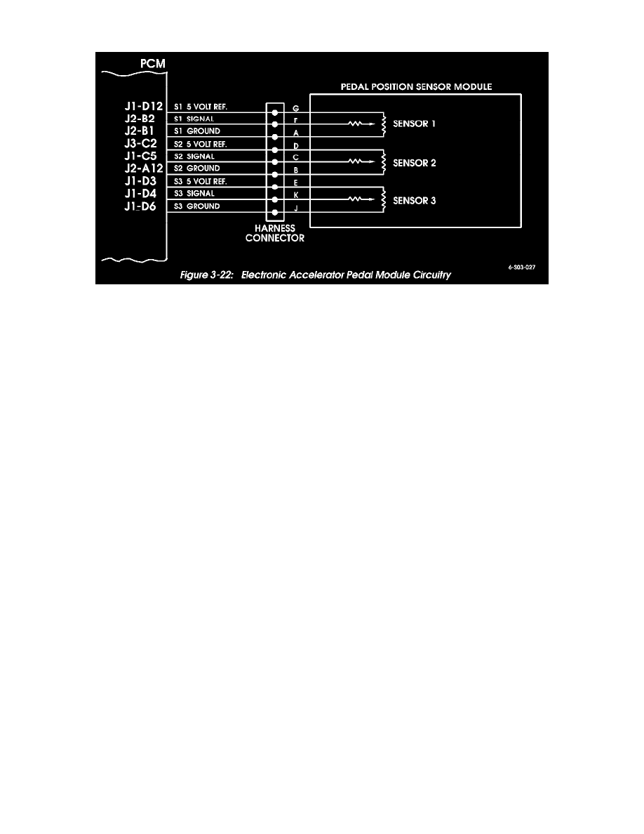
Figure 3-22: Electronic Accelerator Pedal Module Circuitry
Electronic Accelerator Pedal Tests
The pedal module contains three potentiometer-type sensors that provide voltage signals to the PCM. Each potentiometer is scaled differently to provide
varying voltage signals. The PCM compares the voltage variance between them to determine throttle position (Figure 3-22).
A fault in only one of the potentiometer sensors will not cause a trouble code to set. Two or more sensors must develop a fault before the check throttle
light will illuminate.
A fault in two sensors will cause the warning light to illuminate and engine power will be limited by the PCM. A fault in all three sensors, will cause the
PCM to illuminate the light and limit engine speed idle rpm only.
Trouble codes will set under the following circumstances:
-
Two sensors generate voltage of 4.75 volts or more for a minimum of two seconds.
-
Two sensors generate a voltage of 0.25 volts or less for a minimum of two seconds.
-
Voltage difference between sensors 1 and 2 of 6% or more.
-
Voltage difference of 10% or more, between sensors 1, 2, and 3.
-
Fault in all three sensors (above or below normal signal voltage).
The Tech 1 scan tool is required for accurate sensor diagnosis. However, the sensor circuit wires can be tested for shorts, opens, grounds with 12 volt
test lamp and/or multimeter.