
H2 V8-6.0L (2004)
Accessory Delay Module: Initial Inspection and Diagnostic Overview
Diagnostic Starting Point
DIAGNOSTIC STARTING POINT
Begin the system diagnosis with the Diagnostic System Check - Accessory Delay Module. The diagnostic system check will provide the following
information:
-
The identification of the control modules which command the system
-
The ability of the control modules to communicate through the serial data circuit
-
The identification of any stored diagnostic trouble codes DTCs and their status
The use of the Diagnostic System Check will identify the correct procedure for diagnosing the system and where the procedure is located.
Diagnostic System Check
DIAGNOSTIC SYSTEM CHECK
TEST DESCRIPTION
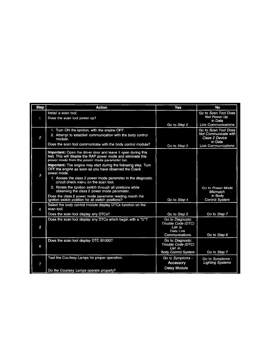
Steps 1-7
The numbers below refer to the step numbers on the diagnostic table.
2. Lack of communication may be due to a partial malfunction of the class 2 serial data circuit or due to a total malfunction of the class 2 serial data
circuit. The specified procedure will determine the particular condition.
3. This step tests for valid system power moding in all ignition switch positions.
5. The presence of DTCs which begin with "U" indicate some other module is not communicating. The specified procedure will compile all the
available information before tests are performed.