
H2 V8-6.2L (2008)
Schematic Reference
*
Cruise Control Schematics (See: Diagrams/Electrical Diagrams)
*
Instrument Cluster Schematics (See: Diagrams/Electrical Diagrams/Instrument Panel, Gauges and Warning Indicators/System Diagram/Instrument
Cluster Schematics)
Connector End View Reference
Component Connector End Views (See: Diagrams/Connector Views/Component Connector End Views)
Description and Operation
*
Cruise Control Description and Operation (See: Description and Operation)
*
Indicator/Warning Message Description and Operation (See: Instrument Panel, Gauges and Warning Indicators/Description and
Operation/Indicator/Warning Message Description and Operation)
Electrical Information Reference
*
Circuit Testing (See: Diagrams/Diagnostic Aids/General Electrical Diagnostic Procedures/Circuit Testing/Circuit Testing)
*
Connector Repairs (See: Diagrams/Diagnostic Aids/General Electrical Diagnostic Procedures/Connector Repairs/Connector Repairs)
*
Testing for Intermittent Conditions and Poor Connections (See: Diagrams/Diagnostic Aids/General Electrical Diagnostic Procedures/Circuit
Testing/Testing For Intermittent and Poor Connections)
*
Wiring Repairs (See: Diagrams/Diagnostic Aids/General Electrical Diagnostic Procedures/Wiring Repairs/Wiring Repairs)
Scan Tool Reference
Programming and Relearning (See: Testing and Inspection/Programming and Relearning) for scan tool information
Circuit/System Verification
Ignition ON, perform the IPC display test using a scan tool. Verify the indicator illuminates and turns OFF.
If the indicator does not operate as expected during this test, replace the IPC.
If the indicator functions normally during this test, replace the ECM/PCM.
Repair Instructions
Perform the Diagnostic Repair Verification (See: Powertrain Management/Computers and Control Systems/Testing and Inspection/Diagnostic Trouble
Code Tests and Associated Procedures/Verification Tests and Procedures) after completing the diagnostic procedure.
Programming and Relearning (See: Testing and Inspection/Programming and Relearning) for ECM, PCM or IPC replacement, setup and programming
Cruise Control Indicator Malfunction (Switch Indicator Malfunction)
Cruise Control Indicator Malfunction (Switch Indicator Malfunction)
Diagnostic Instructions
*
Perform the Diagnostic System Check - Vehicle (See: Testing and Inspection/Initial Inspection and Diagnostic Overview/Diagnostic System
Check - Vehicle) prior to using this diagnostic procedure.
*
Review Strategy Based Diagnosis (See: Testing and Inspection/Initial Inspection and Diagnostic Overview/Strategy Based Diagnosis) for an
overview of the diagnostic approach.
*
Diagnostic Procedure Instructions (See: Testing and Inspection/Initial Inspection and Diagnostic Overview/Diagnostic Procedure Instructions)
provides an overview of each diagnostic category.
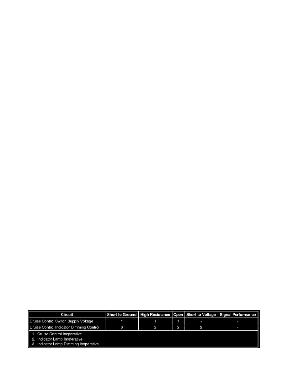
Diagnostic Fault Information
Circuit/System Description