
H3 L5-3.7L (2007)
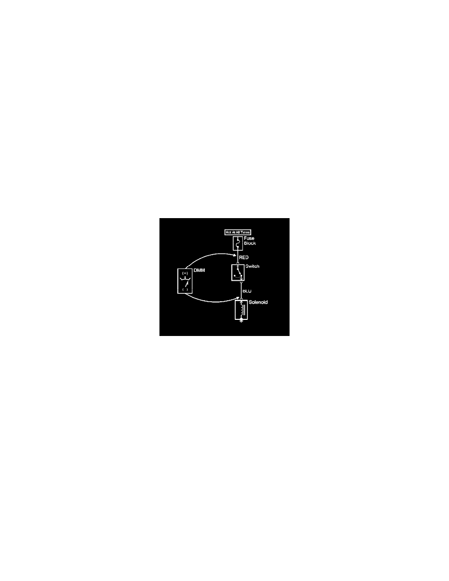
The following procedure measures the voltage at a selected point in a circuit.
1. Disconnect the electrical harness connector for the circuit being tested, if necessary.
2. Enable the circuit and/or system being tested. Use the following methods:
* Turn ON the ignition, with the engine OFF.
* Turn ON the engine.
* Turn ON the circuit and/or system with a scan tool in Output Controls.
* Turn ON the switch for the circuit and/or system being tested.
3. Select the V (AC) or V (DC) position on the DMM.
4. Connect the positive lead of the DMM to the point of the circuit to be tested.
5. Connect the negative lead of the DMM to a good ground.
6. The DMM displays the voltage measured at that point.
Measuring Voltage Drop
Measuring Voltage Drop
Notice: Refer to Test Probe Notice.
The following procedure determines the difference in voltage potential between 2 points.
1. Set the rotary dial of the DMM to the V (DC) position.
2. Connect the positive lead of the DMM to one point of the circuit to be tested.
3. Connect the negative lead of the DMM to the other point of the circuit.
4. Operate the circuit.
5. The DMM displays the difference in voltage between the 2 points.
Probing Electrical Connectors
Probing Electrical Connectors
Important: Always be sure to reinstall the connector position assurance (CPA) and terminal position assurance (TPA) when reconnecting
connectors or replacing terminals.
Frontprobe
Disconnect the connector and probe the terminals from the mating side (front) of the connector.
Important: When probing female 0.64 terminals, it is important to use the correct adapter. There have been some revisions to the test adapter
for 0.64 terminals. The proper adapter for 0.64 terminals is the J35616-64B which has a gold terminal and a black wire between the base and
tip. Failure to use the proper test adapter may result in damage to the terminal being tested and improper diagnosis.
Notice: Do not insert test equipment probes (DVOM etc.) into any connector or fuse block terminal. The diameter of the test probes will deform most
terminals. A deformed terminal will cause a poor connection, which will result in a system failure. Always use the J-35616 GM-Approved Terminal Test
Kit in order to front probe terminals. Do not use paper clips or other substitutes to probe terminals.
When using theJ-35616 GM-Approved Terminal Test Kit, ensure the terminal test adapter choice is the correct size for the connector terminal. Do not