
H3 V8-5.3L (2008)
5. Install the knee bolster bracket. Refer to Driver Knee Bolster Bracket Replacement (Left Hand Drive) (See: Body and Frame/Interior Moulding /
Trim/Dashboard / Instrument Panel/Service and Repair/Driver Knee Bolster Bracket Replacement (Left Hand Drive))Driver Knee Bolster Bracket
Replacement (Right Hand Drive) (See: Body and Frame/Interior Moulding / Trim/Dashboard / Instrument Panel/Service and Repair/Driver Knee
Bolster Bracket Replacement (Right Hand Drive)) .
6. Install the knee bolster. Refer to Driver Knee Bolster Replacement (Left Hand Drive) (See: Body and Frame/Interior Moulding / Trim/Dashboard
/ Instrument Panel/Service and Repair/Driver Knee Bolster Replacement (Left Hand Drive))Driver Knee Bolster Replacement (Right Hand Drive)
(See: Body and Frame/Interior Moulding / Trim/Dashboard / Instrument Panel/Service and Repair/Driver Knee Bolster Replacement (Right Hand
Drive)) .
7. Connect the electrical connector for the brake fluid level sensor.
8. Connect the electrical connectors at the BPMV.
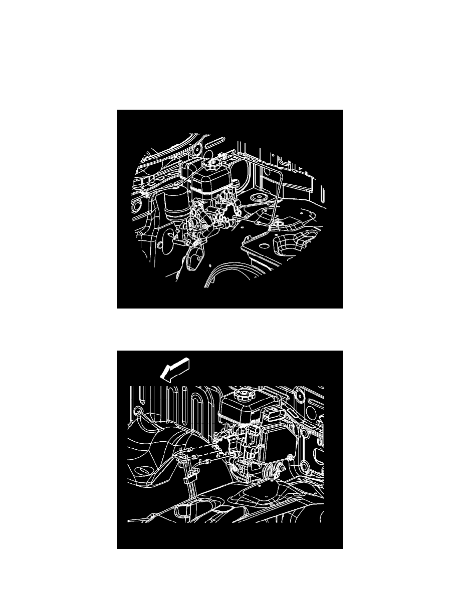
9. Install the right front brake pipe fitting to the master cylinder.
Tighten the fittings to 19 N.m (14 lb ft).
10. Install the rear and left front brake pipe fittings to the brake master cylinder.