Hummer Workshop Service and Repair Manuals
HOME
FEATURES
MENU
INDEX
ABOUT US
Diagram Information and Instructions|Page 3461 >
< Diagram Information and Instructions|Page 3459
H3 V8-5.3L (2008)
Powertrain Management
Relays and Modules - Powertrain Management / Relays and Modules - Computers and Control Systems
Engine Control Module / Component Information
Diagrams / Diagram Information and Instructions
Page 3460
Page 75
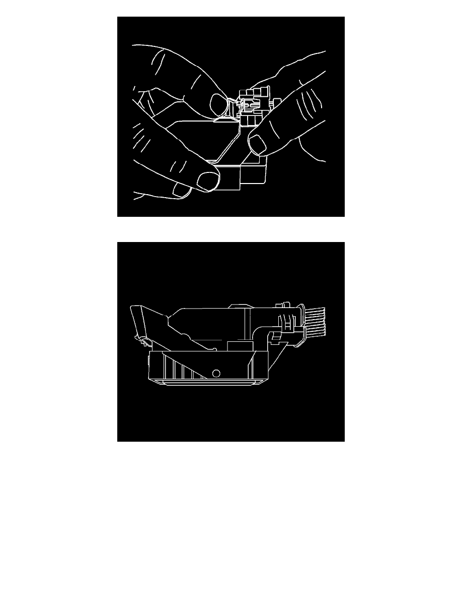
3. The lever should be in the full forward position.
4. Disconnect the connector from the component.
Powertrain Management
Relays and Modules - Powertrain Management / Relays and Modules - Computers and Control Systems
Engine Control Module / Component Information
Diagrams / Diagram Information and Instructions
Page 3460
Diagram Information and Instructions|Page 3461 >
< Diagram Information and Instructions|Page 3459