Hummer Workshop Service and Repair Manuals
HOME
FEATURES
MENU
INDEX
ABOUT US
Diagram Information and Instructions|Page 297 >
< Diagram Information and Instructions|Page 295
H3 V8-5.3L (2008)
Relays and Modules
Relays and Modules - Powertrain Management / Relays and Modules - Computers and Control Systems / Body Control Module / Component Information
Diagrams / Diagram Information and Instructions
Page 296
Page 75
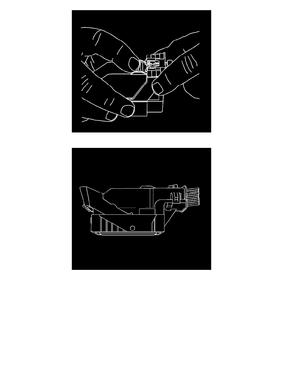
3. The lever should be in the full forward position.
4. Disconnect the connector from the component.
Relays and Modules
Relays and Modules - Powertrain Management / Relays and Modules - Computers and Control Systems / Body Control Module / Component Information
Diagrams / Diagram Information and Instructions
Page 296
Diagram Information and Instructions|Page 297 >
< Diagram Information and Instructions|Page 295