
H3 V8-5.3L (2008)
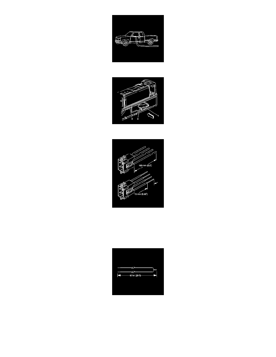
33. Route the deployment harness out of the driver side of the vehicle.
34. Disconnect the I/P module yellow harness connector (1) from the vehicle harness connector (2).
Important: If the vehicle is equipped with dual stage air bags the steering wheel module and I/P module will each have 4 wires. Refer to
Component Connector End Views (See: Diagrams/Connector Views/Component Connector End Views) for determining high and low
circuits.
35. Cut the yellow harness connector out of the vehicle, leaving at least 16 cm (6 in) of wire at the connector.
36. Strip 13 mm (0.5 in) of insulation from each of the connector wire leads.
37. Cut two 6.1 m (20 ft) deployment wires from a 0.8 mm (18 gage) or thicker multi-strand wire. These wires will be used to fabricate the passenger
deployment harness.
38. Strip 13 mm (0.5 in) of insulation from both ends of the wires.
39. Twist together one end from each of the wires in order to short the wires.