
H3 V8-5.3L (2008)
Heated Glass Element: Testing and Inspection
Rear Window Defogger Malfunction
Diagnostic Instructions
*
Perform the Diagnostic System Check - Vehicle (See: Testing and Inspection/Initial Inspection and Diagnostic Overview/Diagnostic System
Check - Vehicle) prior to using this diagnostic procedure.
*
Review Strategy Based Diagnosis (See: Testing and Inspection/Initial Inspection and Diagnostic Overview/Strategy Based Diagnosis) for an
overview of the diagnostic approach.
*
Diagnostic Procedure Instructions (See: Testing and Inspection/Initial Inspection and Diagnostic Overview/Diagnostic Procedure Instructions)
provides an overview of each diagnostic category.
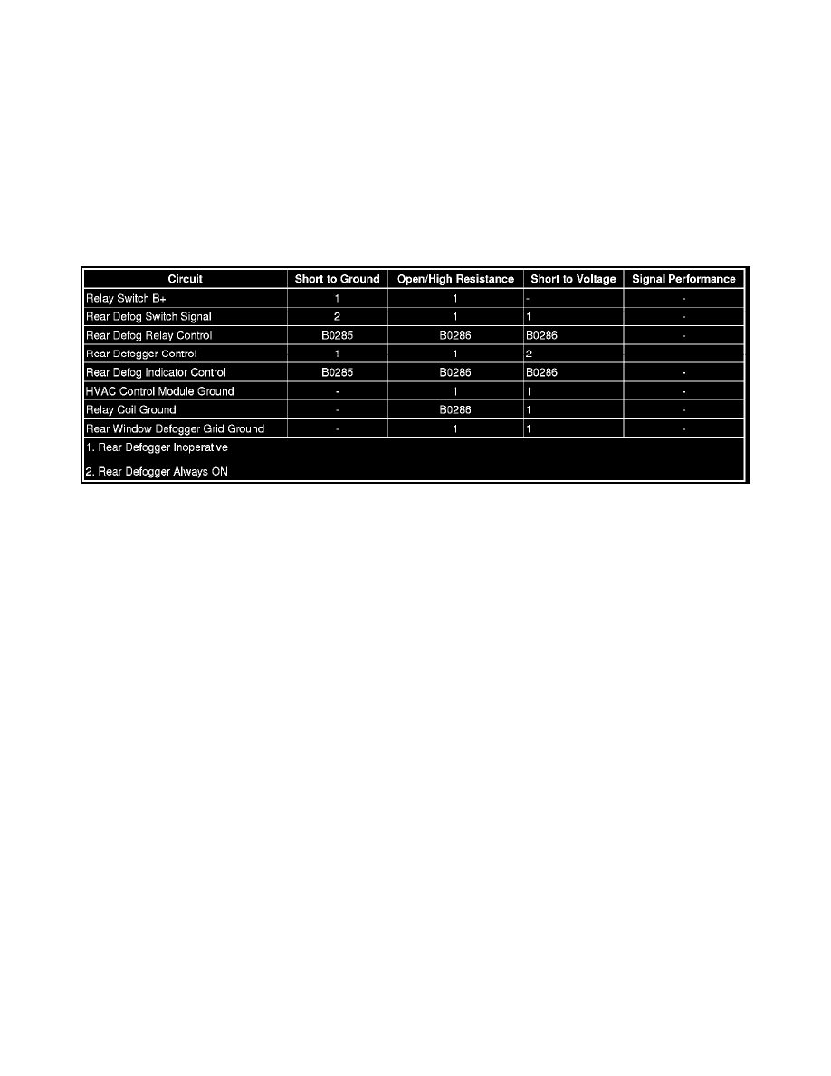
Diagnostic Fault Information
Circuit/System Description
With the ignition in the RUN position, and the rear window defogger switch depressed, a signal is sent from the HVAC control module to the body
control module (BCM) requesting rear defog operation. The BCM responds by providing voltage to the rear defog indicator and for the RR DEFOG
relay. The RR DEFOG relay then provides voltage to the rear defog element supply voltage circuit operating the rear defog system.
Reference Information
Schematic Reference
Defogger Schematics (See: Diagrams/Electrical Diagrams)
Connector End View Reference
Component Connector End Views (See: Diagrams/Connector Views/Component Connector End Views)
Description and Operation
Rear Window Defogger Description and Operation (See: Description and Operation)
Electrical Information Reference
*
Circuit Testing (See: Diagrams/Diagnostic Aids/General Electrical Diagnostic Procedures/Circuit Testing/Circuit Testing)
*
Connector Repairs (See: Diagrams/Diagnostic Aids/General Electrical Diagnostic Procedures/Connector Repairs/Connector Repairs)
*
Testing for Intermittent Conditions and Poor Connections (See: Diagrams/Diagnostic Aids/General Electrical Diagnostic Procedures/Circuit
Testing/Testing For Intermittent and Poor Connections)
*
Wiring Repairs (See: Diagrams/Diagnostic Aids/General Electrical Diagnostic Procedures/Wiring Repairs/Wiring Repairs)
Scan Tool Reference
Control Module References (See: Testing and Inspection/Programming and Relearning) for scan tool information
Circuit/System Verification
1. Ignition ON, observe the scan tool Rear Defog Switch parameter while pressing the rear window defogger switch. The parameter should change
between Active and Inactive.
‹› If the parameter does not change between the commanded states, refer to Rear Window Defogger Switch Malfunction.