
Accent L4-1.6L (2003)
Ignition Coil: Diagnostic Aids
TROUBLESHOOTING PROCEDURES
The following five-steps troubleshooting procedure is recommended.
1. Verify the customer's complaints
Turn on all the components in the problem circuit to check the accuracy of the customer's complaints. Note the symptoms. Do not begin
disassembly or testing until you have narrowed down the probable causes.
2. Read and analyze the schematic diagram
Locate the schematic for the problem circuit. Determine how the circuit is supposed to work by tracing the current paths from the power source
through the system components to ground. If you do not understand how the circuit should work, read the circuit operation text. Also check other
circuits that share with the problem circuit. The name of circuits that share the same fuse, ground, or switch, for example, are referred to on each
diagram. Try to operate any shared circuits you did not check in step 1. if the shared circuit works, the shared wiring is okay, and the cause must
be within the wiring used only by the problem circuit. If several circuits fail at the same time, the fuse or ground is a likely cause.
3. Inspect the circuit/component with the problem isolated
Make a circuit test to check the diagnosis you made in step 2. Remember that a logical, simple procedure is the key to efficient troubleshooting.
Narrow down the probable causes using the troubleshooting hints and system diagnosis charts. Test for the most likely cause of failure first. Try to
make tests at points that are easily accessible.
4. Repair the problem
Once the problem is found, make the necessary repairs.
5. Make sure the circuit works
Repeat the system check to be sure you have repaired the problem. If the problem was a blown fuse, be sure to test all of the circuits on that fuse.
TROUBLESHOOTING EQUIPMENT
VOLTMETER AND TEST LAMP
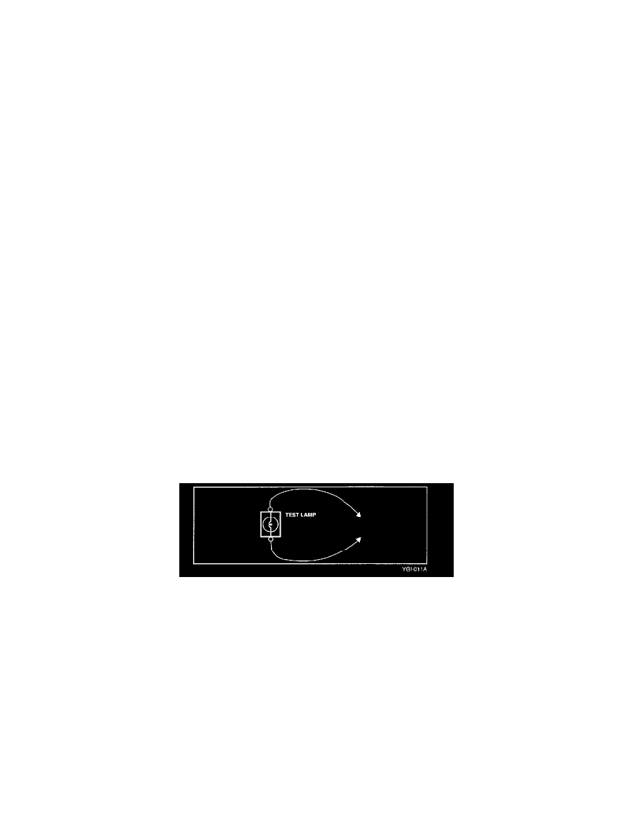
Use a test lamp or a voltmeter on circuits without solid-state units and use a test lamp to check for voltage. A test lamp is made up of a 12-Volt light bulb
with a pair of leads attached. After grounding one lead, touch the other lead to various points along the circuit where voltage should be present. When the
bulb goes on, there is voltage at the point being tested.
CAUTION: A number of circuits include solid-state modules, such as the Engine Control Module(ECM), used with computer command control
injection. Voltage in these circuits should be tested only with a 10-megaohm or higher impedance digital volt-meter . Never use a test lamp on circuits
that contain solid state modules. Damage to the modules may result.
A voltmeter can be used in place of a test lamp. While a test lamp shows whether the voltage is present or not, a voltmeter indicates how much voltage is
present.
SELF-POWERED TEST LAMP AND OHMMETER
Use a self-powered test lamp or an ohmmeter to check for continuity. The ohmmeter shows how much resistance there is between two points along a
circuit. Low resistance means good continuity.
CAUTION: Never use a self-powered test lamp on circuits that contain solid state modules. Damage to these modules may result.
An ohmmeter can be used in place of a self-powered test lamp. The ohmmeter shows how much resistance there is between two points along a circuit.
Low resistance means good continuity.