
Accent L4-1.6L (2003)
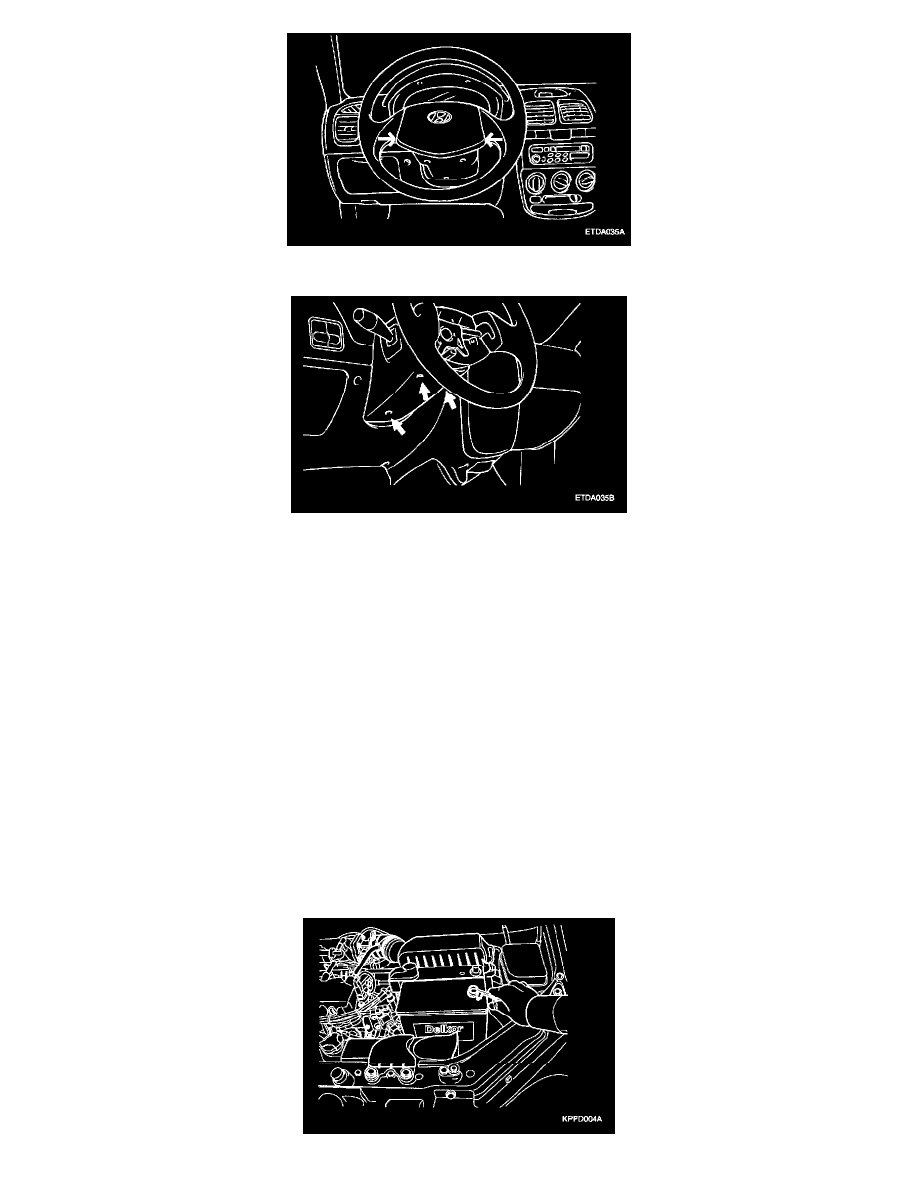
1. Remove the horn pad and steering wheel.
2. Remove the upper and lower steering column shrouds.
3. Remove the multifunction switch assembly mounting screws and remove the multifunction switch assembly.
4. Installation is the reverse of removal.
WITH AIR BAG
Prior to removing of the multifunction switch assembly in vehicles equipped with air bags, be careful to keep the following items.
CAUTION:
-
Never attempt to disassemble or repair the air bag module or clock spring. If faulty, replace it.
-
Do not drop the air bag module or clock spring or allow contact with water, grease or oil Replace if a dent, crack, deformation or rust are detected.
-
The air bag module should be stored on a fiat surface and placed so that the pad surface is facing upward. Do not place anything on top of it.
-
Do not expose the air bag module to temperatures over 93 °C (200 °F).
-
After deployment of an air bag, replace the clock spring with a new one.
-
Wear gloves and safety glasses when handling an air bag that has already been deployed.
-
An undeployed air bag module should only be disposed of in accordance with the procedures mentioned in the Restraints section.
-
When you disconnect the air bag module-clock spring connector, take care not to apply excessive force to it.
-
The removed air bag module should be stored in a clean, dry place.
-
Prior to installing the clock spring, align the mating mark and "NEUTRAL", position indicator of the clock spring, and, after turning the front
wheels to the straight-ahead position, install the clock spring to the column switch. If the mating mark of the clock spring is not properly aligned,
the steering wheel may not completely rotate during a turn, or the flat cable within the clock spring may be severed, obstructing normal operation
of the SRS and possibly leading to serious injury to the vehicle's driver. To inspect the clock spring, refer to the Restraints section.