
Accent GL Hatchback L4-1.6L (2002)
A voltmeter can be used in place of a test lamp. While a test lamp shows whether the voltage is present or not, a voltmeter indicates how much voltage is
present.
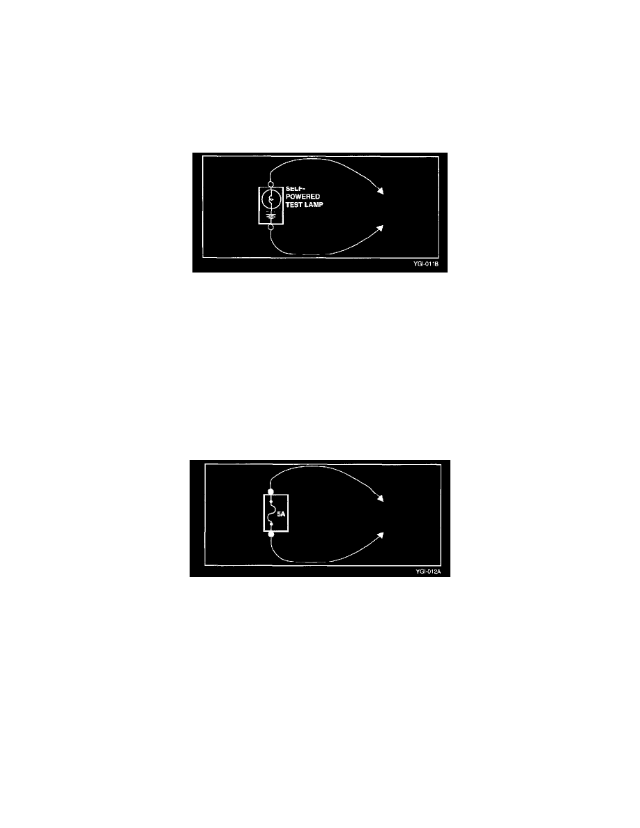
SELF-POWERED TEST LAMP AND OHMMETER
Use a self-powered test lamp or an ohmmeter to check for continuity. The ohmmeter shows how much resistance there is between two points along a
circuit. Low resistance means good continuity.
CAUTION: Never use a self-powered test lamp on circuits that contain solid state modules. Damage to these modules may result
An ohmmeter can be used in place of a self-powered test lamp. The ohmmeter shows how much resistance there is between two points along a circuit.
Low resistance means good continuity.
Circuits which include any solid-state devices should be tested only with a 10-mega Ohm or higher impedance digital multimeter. When measuring
resistance with a digital multimeter, the battery negative terminal should be disconnected. Otherwise, there may incorrect readings. Diodes and
solid-state devices in a be circuit can make an ohmmeter give a false reading. To find out if a component is affecting a measurement, take one reading,
reverse the leads and take a second reading. If different the solid-state device is affecting the measurement.
JUMPER WIRE WITH FUSE
Use a jumper wire with a fuse to by-pass an open circuit.
A jumper wire is made up of an in-line fuse holder connected to a set of test leads. This tool is available with small clamp connectors providing adaption
to most connectors without damage.
CAUTION: Do not use a fuse with a higher rating than the specified fuse that protects the circuit being tested. Do not use this tool in any situation to
substitute an input or output at the solid-state control module, such as ECM, TCM, etc.
SHORT FINDER
A short finder is available to locate a short to ground. The short finder creates a pulsing magnetic field in the shorted circuit and shows you the location
of the short through body trim or sheet metal.
Troubleshooting Procedures
The following five-step troubleshooting procedure is recommended.
1. Verify the customer's complaints
Turn on all the components in the problem circuit to check the accuracy of the customer's complaints. Note the symptoms. Do not begin
disassembly or testing until you have narrowed down the probable causes.
2. Read and analyze the schematic diagram
Locate the schematic for the problem circuit. Determine how the circuit is supposed to work by tracing the current paths from the power source