
Accent L L4-1495cc 1.5L SOHC MFI (2001)
Oxygen Sensor: Diagnostic Aids
Checking Cables and Wires
1. Check the terminal for tightness.
2. Check terminals and wires for corrosion from battery electrolyte, etc.
3. Check terminals and wires for open circuits.
4. Check wire insulation and coating for damage, cracks and degrading.
5. Check the conductive parts of terminals for contact with other metallic parts (vehicle body and other parts).
6. Check grounded parts to verify that there is complete continuity between their attaching bolt(s) and the vehicle's body.
7. Check for incorrect wiring.
8. Check that the wiring is so clamped to prevent contact with sharp corners of the vehicle body, etc. or hot parts (exhaust manifold, etc.)
9. Check that the wiring is clamped firmly to provide enough clearance from the fan pulley, fan belt and other rotating or moving parts.
10. Check that the wiring has a little space so that it can vibrate between fixed and moving parts such as the vehicle body and the engine.
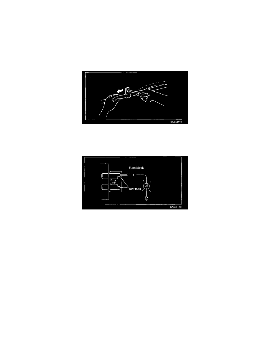
Checking Fuses
A blade type fuse has test taps provided to allow checking the fuse itself without removing it from the fuse block. The fuse is good if the test lamp lights
up when one lead is connected to the test taps (one at a time) and the other lead is grounded. (Turn the ignition switch so that the fuse circuit becomes
operative.)
Five Step Troubleshooting Procedure
The following five-step troubleshooting procedure is recommended.
1. Verify the customer's complaints
Turn on all the components in the problem circuit to check the accuracy of the customer's complaints. Note the symptoms. Do not begin
disassembly or testing until you have narrowed down the probable causes.
2. Read and analyze the schematic diagram
Locate the schematic for the problem circuit. Determine how the circuit is supposed to work by tracing the current paths from the power source
through the system components to ground. If you do not understand how the circuit should work, read the circuit operation text. Also check other
circuits that share with the problem circuit. The name of circuits that share the same fuse, ground, or switch, for example, are referred to on each
diagram. Try to operate any shared circuits you did not check in step 1. If the shared circuit works, the shared wiring is okay, and the cause must
be within the wiring used only by the problem circuit. If several circuits fail at the same time, the fuse or ground is a likely cause.
3. Inspect the circuit/component with the problem isolated
Make a circuit test to check the diagnosis you made in step 2. Remember that a logical, simple procedure is the key to efficient troubleshooting.
Narrow down the probable causes using the troubleshooting hints and system diagnosis charts. Test for the most likely cause of failure first. Try to
make tests at points that are easily accessible.
4. Repair the problem
Once the problem is found, make the necessary repairs.