
Accent L L4-1495cc 1.5L SOHC MFI (2001)
5. Install the clip pin and self lock pin. (shift lever side).
6. Connect the position indicator light connector, the O/D switch connector, the parking position switch connector, normal/economy select switch
connector and the shift lock solenoid connector.
7. Install the shift lever indicator assembly.
8. Apply the specified grease at the place shown in the figure.
Specified grease: Chassis grease SAE J310, NLGI No.2
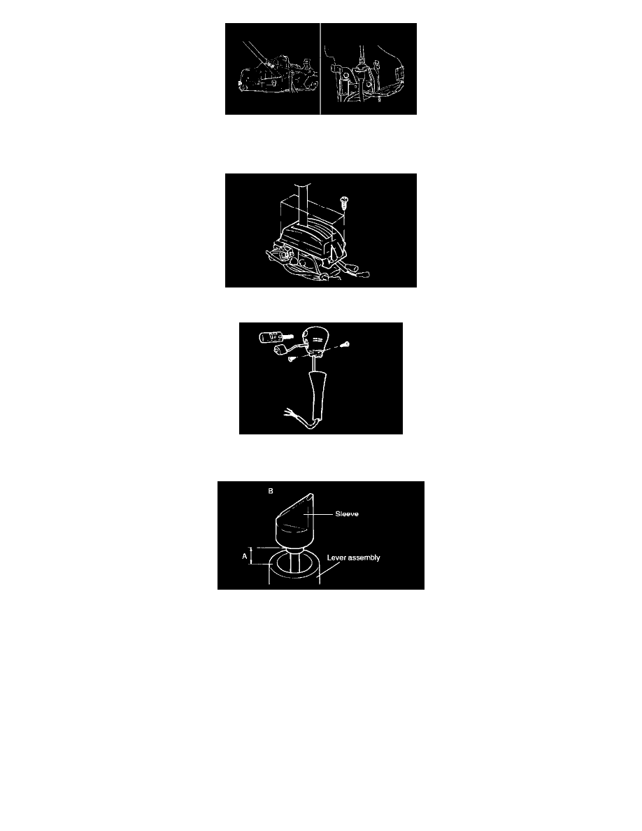
9. Place the shift lever in the N position, and then turn the cam adjusting so that the clearance between the cam adjusting and the lever assembly end
in within the standard value.
Standard value (A): 15.2 - 15.9 mm (0.598 - 0.625 inch)
NOTE Be sure to face B of the adjusting cam to the push button (driver's side).
10. Insert the O/D switch wiring to the shift lever cover, and then assemble the pin into the O/D switch connector.
11. Install the selector knob assembly.
NOTE When replacing with a new one, remove the new 3 connector pins first.