
Elantra GT Hatchback L4-2.0L (2002)
circuits that share with the problem circuit. The name of circuits that share the same fuse, ground, or switch, for example, are referred to on each
diagram. Try to operate any shared circuits you did not check in step 1. if the shared circuit works, the shared wiring is okay, and the cause must
be within the wiring used only by the problem circuit. If several circuits fail at the same time, the fuse or ground is a likely cause.
3. inspect the circuit/component with the problem isolated
Make a circuit test to check the diagnosis you made in step 2. Remember that a logical, simple procedure is the key to efficient troubleshooting.
Narrow down the probable causes using the troubleshooting hints and system diagnosis charts. Test for the most likely cause of failure first. Try to
make tests at points that are easily accessible.
4. Repair the problem
Once the problem is found, make the necessary repairs.
5. Make sure the circuit works
Repeat the system check to be sure you have repaired the problem. If the problem was a blown fuse, be sure to test all of the circuits on that fuse.
Troubleshooting Test
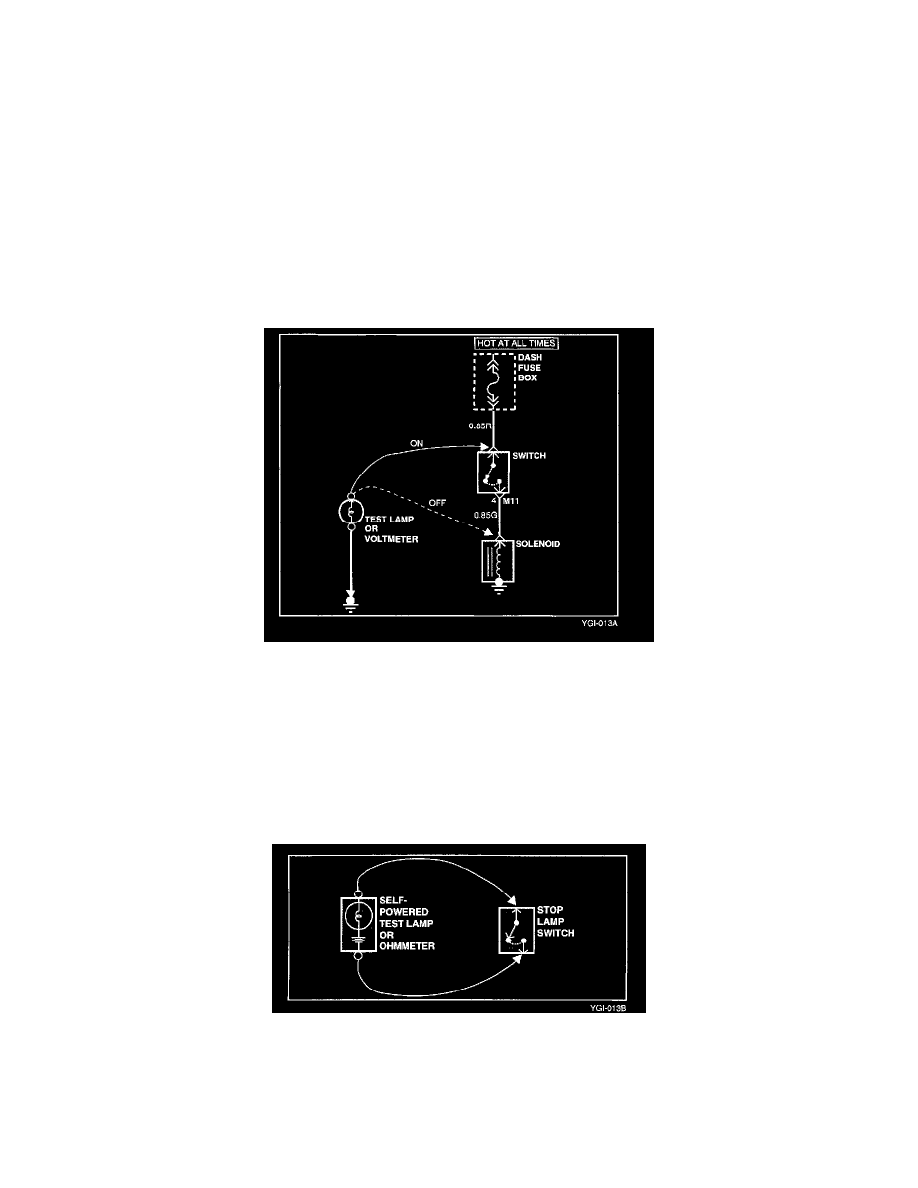
TESTING FOR VOLTAGE
This test measures voltage in a circuit. When testing for voltage at a connector, you do not have to separate the two halves of the connector instead,
probe the connector from the back (backprobe). Always check both sides of the connector because dirt and corrosion between its contact surfaces can
cause electrical problems.
1. Connect one lead of a test lamp or voltmeter to a ground. If you are using a voltmeter, be sure it is the voltmeter's negative test lead you have
connected to ground.
2. Connect the other lead of the test lamp or voltmeter to a selected test point (connector or terminal).
3. If the test lamp glows, there is voltage present. If you are using a voltmeter, note the voltage reading. A loss of more than 1 volt from specification
indicates a problem.
TESTING FOR CONTINUITY
1. Disconnect the battery negative terminal.
2. Connect one lead of a self-powered test lamp or ohmmeter to one end of the part of the circuit you wish to test. If you are using an ohmmeter, hold
the leads together and adjust the ohmmeter to read zero ohms.
3. Connect the other lead to the other end.
4. If the self-power test lamp glows, there is continuity. If you are using an ohmmeter, low or zero resistance means good continuity.