
Genesis Coupe L4-2.0L Turbo (2010)
-
The connector figure of components in the schematic diagram by system is indicated on the last page of schematic diagram.
-
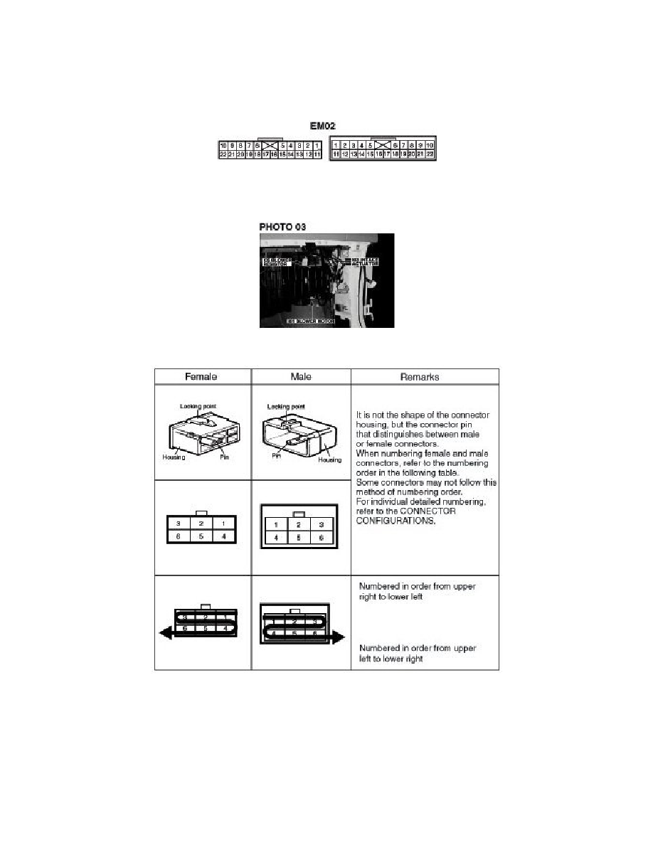
It shows the front of the connector on the harness side when not to the harness connector. The terminal number on each connector can be
obtained by following the pattern used in (5) connector view and numbering order. Unused terminals are marked with an asterisk (*).
3. Connector configurations (connection between harnesses)
-
When connecting the harness with connector between harnesses, it shows female and male connectors and indicates them on the connector
configurations group.
4. Component locations
-
To find the components easily, a components locations diagram is indicated with "PHOTO NO" on the lower portion of the component name.
-
To make it easy to distinguish connectors, the connector in the picture is indicated being installed in the vehicle.
5. Connector view and numbering order
NOTE: UNLESS OTHERWISE STATED, ALL CONNECTOR VIEWS ARE FROM THE TERMINAL SIDE OF THE CONNECTOR.
6. WIRE COLOR ABBREVIATIONS
The following abbreviations are used to identify wire colors in the circuit schematics.