
Santa Fe L4-2.4L (2001)
Camshaft Position Sensor: Diagnostic Aids
Checking Cables and Wires
1. Check the terminal for tightness.
2. Check terminals and wires for corrosion from battery electrolyte, etc.
3. Check terminals and wires for open circuits.
4. Check wire insulation and coating for damage, cracks and degrading.
5. Check the conductive parts of terminals for contact with other metallic parts (vehicle body and other parts).
6. Check grounded parts to verify that there is complete continuity between their attaching bolt(s) and the vehicle's body.
7. Check for incorrect wiring.
8. Check that the wiring is clamped firmly to prevent contact with sharp corners of the vehicle body, etc. or hot parts (exhaust manifold, etc.)
9. Check that the wiring is clamped firmly to provide enough clearance from the fan pulley, fan belt and other rotating or moving parts.
10. Check that the wiring has a little space so that it can vibrate between the fixed and moving parts such as the vehicle body and the engine.
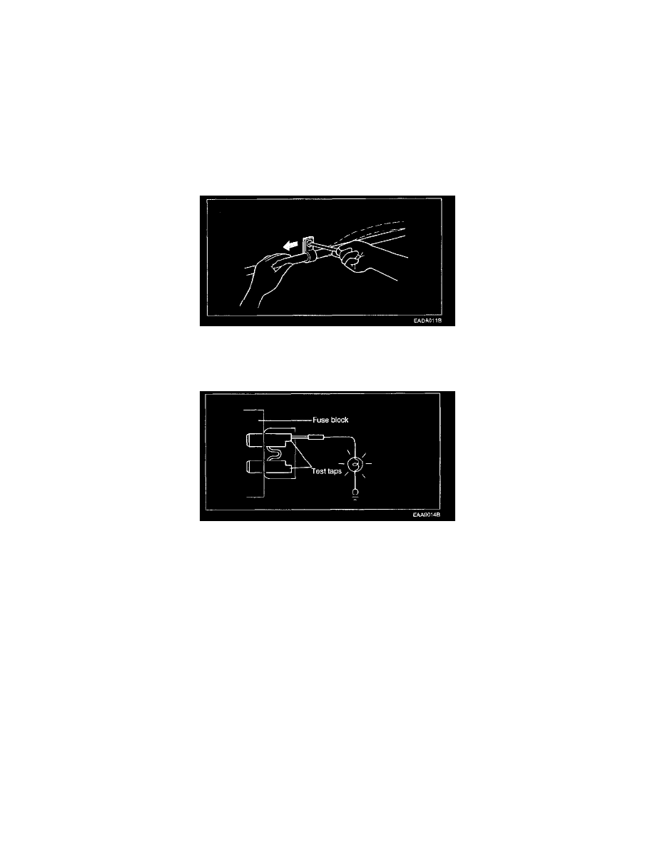
Checking Fuses
CHECKING FUSES
A blade type fuse has test taps provided to allow checking the fuse itself without removing it from the fuse block. The fuse is good if the test lamp lights
up when its one lead is connected to the test taps (one at a time) and the other lead is grounded. (Turn the ignition switch so that the fuse circuit becomes
operative.)
Troubleshooting Equipment
VOLTMETER AND TEST LAMP
Use a test lamp or a voltmeter on circuits without solid-state units and use a test lamp to check for voltage. A test lamp is made up of a 12-volt light bulb
with a pair of leads attached. After grounding one lead, touch the other lead to various points along the circuit where voltage should be present. When the
bulb goes on, there is voltage at the point being tested.
CAUTION: A number of circuits include solid-state modules, such as the Engine Control Module (ECM), used with computer command control
injection. Voltage in these circuits should be tested only with a 10-megaohm or higher impedance digital voltmeter. Never use a test lamp on circuits that
contain solid-state modules. Damage to the modules may result.