
Santa Fe L4-2.4L (2001)
The following five-step troubleshooting procedure is recommended.
1. Verify the customer's complaints
Turn on all the components in the problem circuit to check the accuracy of the customer's complaints. Note the symptoms. Do not begin
disassembly or testing until you have narrowed down the probable causes.
2. Read and analyze the schematic diagram
Locate the schematic for the problem circuit. Determine how the circuit is supposed to work by tracing the current paths from the power source
through the system components to ground. If you do not understand how the circuit should work, read the circuit operation text. Also check other
circuits that share with the problem circuit. The name of circuits that share the same fuse, ground, or switch, for example, are referred to on each
diagram. Try to operate any shared circuits you did not check in step 1. If the shared circuit works, the shared wiring is okay, and the cause must
be within the wiring used only by the problem circuit. If several circuits fail at the same time, the fuse or ground is a likely cause.
3. Inspect the circuit/component with the problem isolated
Make a circuit test to check the diagnosis you made in step 2. Remember that a logical, simple procedure is the key to efficient troubleshooting.
Narrow down the probable causes using the troubleshooting hints and system diagnosis charts. Test for the most likely cause of failure first. Try to
make tests at points that are easily accessible.
4. Repair the problem
Once the problem is found, make the necessary repairs.
5. Make sure the circuit works
Repeat the system check to be sure you have repaired the problem. If the problem was a blown fuse, be sure to test all of the circuits on that fuse.
Troubleshooting Test
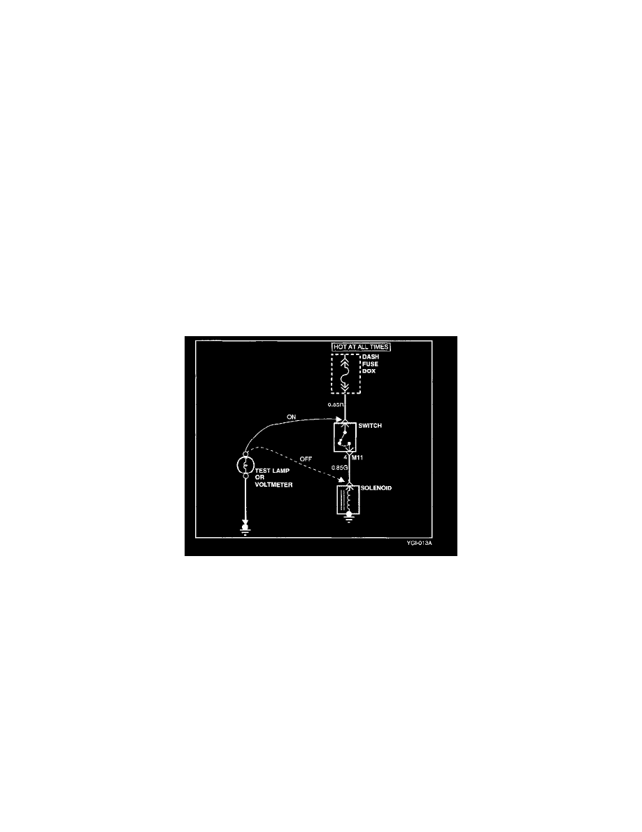
TESTING FOR VOLTAGE
This test measures voltage in a circuit. When testing for voltage at a connector, you do not have to separate the two halves of the connector Instead,
probe the connector from the back (backprobe). Always check both sides of the connector because dirt and corrosion between its contact surfaces can
cause electrical problems.
1. Connect one lead of a test lamp or voltmeter to a ground. If you are using a voltmeter, be sure it is the voltmeter's negative test lead you have
connected to ground.
2. Connect the other lead of the test lamp or voltmeter to a selected test point (connector or terminal).
3. If the test lamp glows, there is voltage present. If you are using a voltmeter, note the voltage reading. Too close a loss of more than 1 volt from
specification indicates a problem.