
Santa Fe L4-2.4L (2001)
Knock Sensor: Diagram Information and Instructions
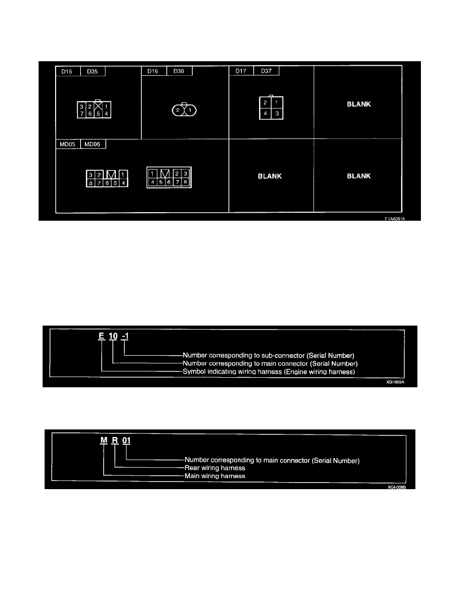
Connector Configurations
Connector Configurations
This information shows the cavity or terminal locations in all the multi-pin connectors shown in the schematic diagrams. It will help you to locate check
points, together with the wire colors and terminal numbers in the schematic. The configuration drawings show the connector view as seen from a
component after the harness connector has been disconnected. When more than one connector is connected to a component, the connectors are all shown
together. Both halves of in-line connectors are shown together.
Connector Identification
A connector identification symbol consists of a wiring harness location classification symbol corresponding to a wiring harness location and number
corresponding to the connector. These connector locations can be found in the HARNESS LAYOUTS.
For example:
NOTE: Connectors which connect each wiring harness are represented by the following symbols.
For example: