
Santa Fe FWD V6-2.7L (2007)
Circuit Diagram
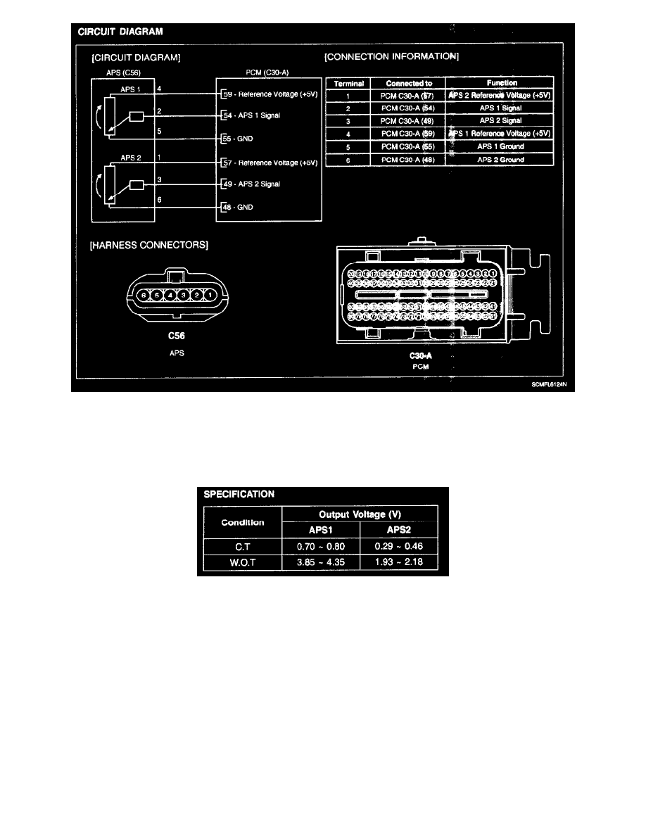
CIRCUIT DIAGRAM
COMPONENT INSPECTION
1. Connect a scantool on Diagnosis Link Connector (DLC).
Specification
2. Start engine and check output voltages of APS 1 and 2 at C.T and W.O.T.
3. Turn ignition switch OFF and disconnect the scantool from the DLC.
4. Disconnect APS connector and measure resistance between APS terminals 5 and 6 (APS 1..
Specification: Refer to SPECIFICATION.