
Santa Fe FWD V6-2.7L (2007)
Relay Box: Testing and Inspection
Relay Box (Instrument Panel)
RELAY BOX (INSTRUMENT PANEL)
INSPECTION
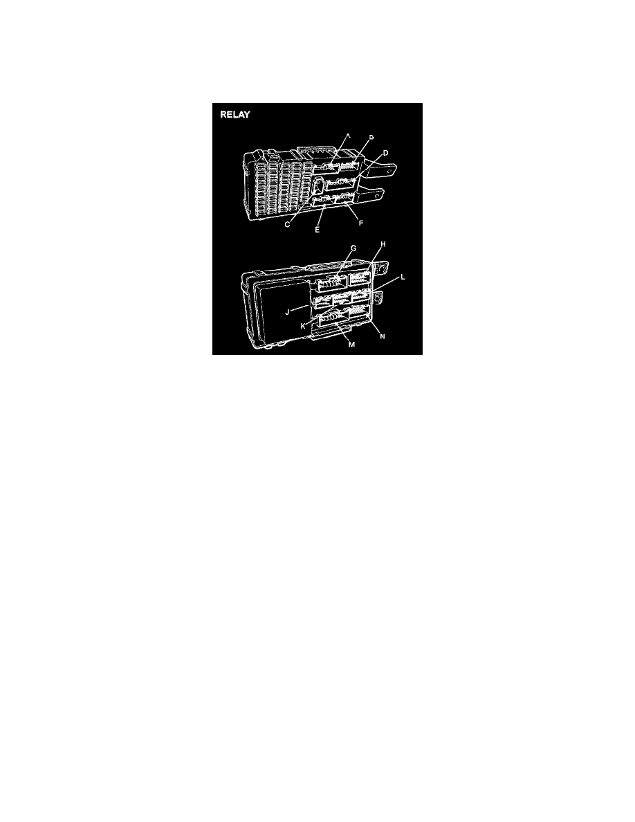
RELAY
DOOR LOCK
1. There should be continuity between the No. 5 in the I/P-J and No. 18 terminals in the I/P-D when power and ground are connected to the No. 2
terminal in the I/P-C and No. 9 terminal in the I/P-J.
2. There should be no continuity between the No. 5 terminal in the I/P-J and No. 18 terminal in the I/P-D when power is disconnected.
DOOR UNLOCK
1. There should be continuity between the No. 5 terminal in the I/P-J and No. 7 terminal in the I/P-K when power and ground are connected to the
No. 2 terminal in the I/P-C and No. 1 terminal in the I/P-K.
2. There should be no continuity between the No. 5 terminal in the I/P-J and No. 7 terminal in the I/P-D when power is disconnected.
POWER WINDOW
1. There should be continuity between the No. 6 in the I/P-F and No. 14 terminal in the I/P-D when power and ground are connected to the No. 10
terminal in the I/P-E and No. 2 terminal in the I/P-J.
2. There should be no continuity between the No. 6 terminal in the I/P-F and No. 14 terminal in the I/P-D when power is disconnected.
HAZARD LAMP RELAY
1. There should be continuity between the No. 2 of I/P-C and No. 3 or No. 4 of I/P-E terminals when power and ground are connected to the No. 2 of
I/P-C and No. 6 of I/P-G terminals.
2. There should be no continuity between the No. 2 of I/P-C and No. 3 or No. 4 of I/P-E terminals when power is disconnected to the No. 2 of I/P-C
and No. 6 of I/P-G terminals.
BURGLAR ALARM HORN
1. There should be continuity between the No. 1 of I/P-C and No. 6 of I/P-J terminals when power and ground are connected to the No. 1 of I/P-C
and No. 8 of I/P-J terminals.
2. There should be no continuity between the No. 1 of I/P-C and No. 6 of I/P-J terminals when power is disconnected to the No. 1 of I/P-C and No. 8
of I/P-J terminals.
BURGLAR ALARM START
1. There should be continuity between the No. 10 of I/P-M and N0. 9 of I/P-K terminals when power and ground are connected to the No. 10 of
I/P-M and No. 3 of I/P-A terminals.
2. There should be no continuity between the No. 10 of I/P-M and No. 9 of I/P-K terminals when power is disconnected to the No. 10 of I/P-M and
No. 3 of I/P-A terminals.
BLOW