
Santa Fe FWD V6-3.3L (2009)
2. Checking Point for Connector
A. While the connector is connected:
Hold the connector, check connecting condition and locking efficiency.
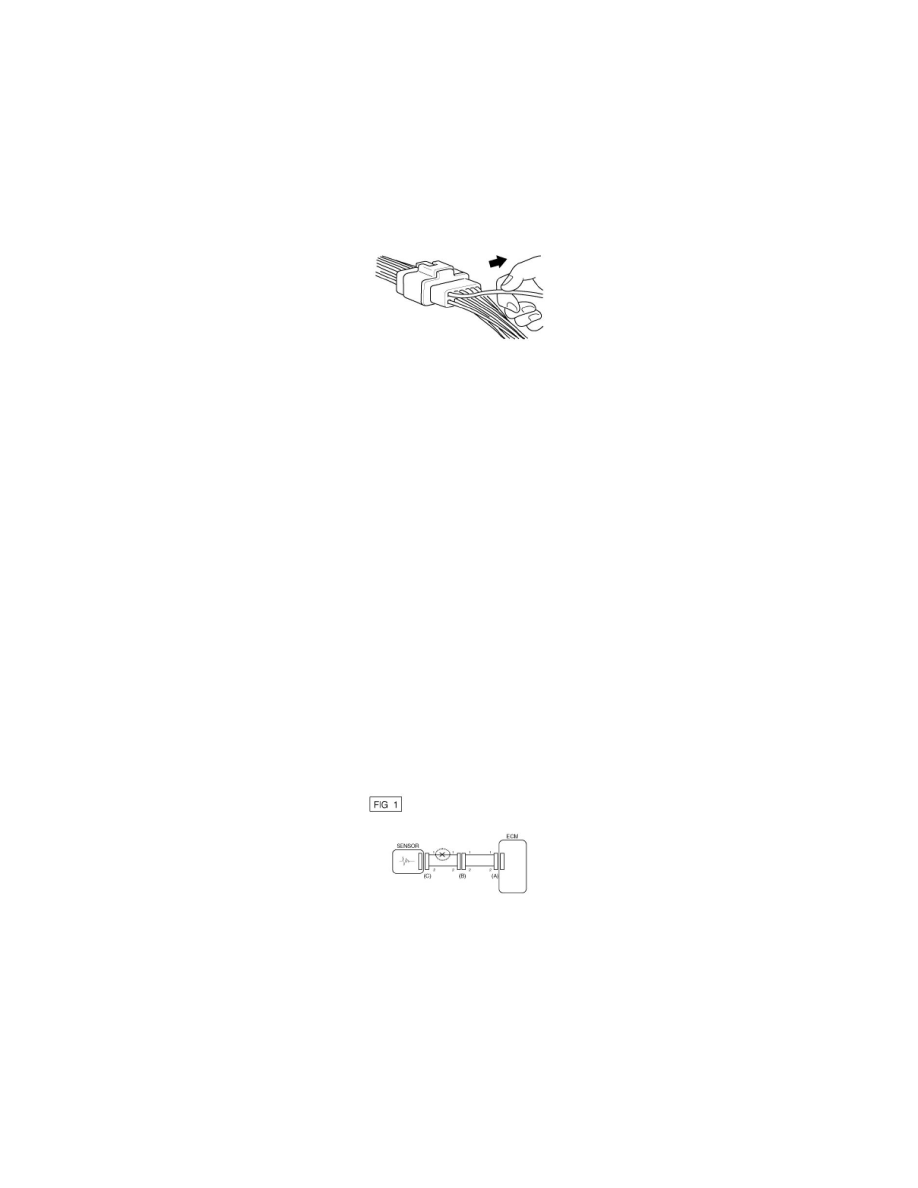
B. When the connector is disconnected:
Check missed terminal, crimped terminal or broken core wire by slightly pulling the wire harness.
Visually check for rust, contamination, deformation and bend.
C. Check terminal tightening condition:
Insert a spare male terminal into a female terminal, and then check terminal tightening conditions.
D. Pull lightly on individual wires to ensure that each wire is secured in the terminal.
3. Repair Method of Connector Terminal
A. Clean the contact points using air gun and/or shop rag.
NOTE:
Never use sand paper when polishing the contact points, otherwise the contact point may be damaged.
B. In case of abnormal contact pressure, replace the female terminal.
Wire Harness Inspection Procedure
1. Before removing the wire harness, check the wire harness position and crimping in order to restore it correctly.
2. Check whether the wire harness is twisted, pulled or loosened.
3. Check whether the temperature of the wire harness is abnormally high.
4. Check whether the wire harness is rotating, moving or vibrating against the sharp edge of a part.
5. Check the connection between the wire harness and any installed part.
6. If the covering of wire harness is damaged; secure, repair or replace the harness.
Electrical Circuit Inspection Procedure
X Check Open Circuit
1. Procedures for Open Circuit
A. Continuity Check
B. Voltage Check
If an open circuit occurs (as seen in [FIG. 1]), it can be found by performing Step 2 (Continuity Check Method) or Step 3 (Voltage Check Method)
as shown below.
2. Continuity Check Method
NOTE:
When measuring for resistance, lightly shake the wire harness above and below or from side to side.
Specification (Resistance)
1Ohms or less -> Normal Circuit
1MOhms or Higher -> Open Circuit
A. Disconnect connectors (A), (C) and measure resistance between connector (A) and (C) as shown in [FIG. 2].