
Scoupe L4-1468cc 1.5L SOHC VIN J MFI (1994)
Throttle Position Sensor: Diagnostic Aids
Five Step Troubleshooting Procedure
Step 1. Verify the customer complaints
Turn ON all the components in the problem circuit to check the accuracy of the customer complaints. Note the Symptoms. Do not begin disassembly or
testing until you have narrowed down the probable causes.
Step 2. Read and analyze the electrical diagram
Locate the electrical diagram for the problem circuit. Determine how the circuit is supposed to work by tracing the current paths from the power source
through the system components to ground. If you do not understand how the circuit should work, read the circuit operation text. Also check other circuits
that share with the problem circuit. The name of circuits that share the same fuse, ground or switch, for example, are referred to on each diagrams. Try to
operate any shared circuits you did not check in step 1. If the shared circuit works, the shared wiring is okay, and the cause must be within the wiring
used only by the problem circuit. If several circuit fails at the same time, the fuse or ground is a likely cause.
Step 3. Inspect the circuit/component with the problem isolated
Make a circuit test to check the diagnosis you made in step 2. Remember that a logical, simple procedure is the key to efficient troubleshooting. Narrow
down the probable causes using the troubleshooting hints, system diagnosis charts. Test for the most likely cause of failure first and try to make tests at
points that are easily accessible.
Step 4. Repair the problem
Once the problem is found, make the necessary repairs.
Step 5. Make sure the circuit works
Repeat the system check to be sure you have repaired the problem. If the problem was a blown fuse, be sure to test all of the circuits on that fuse.
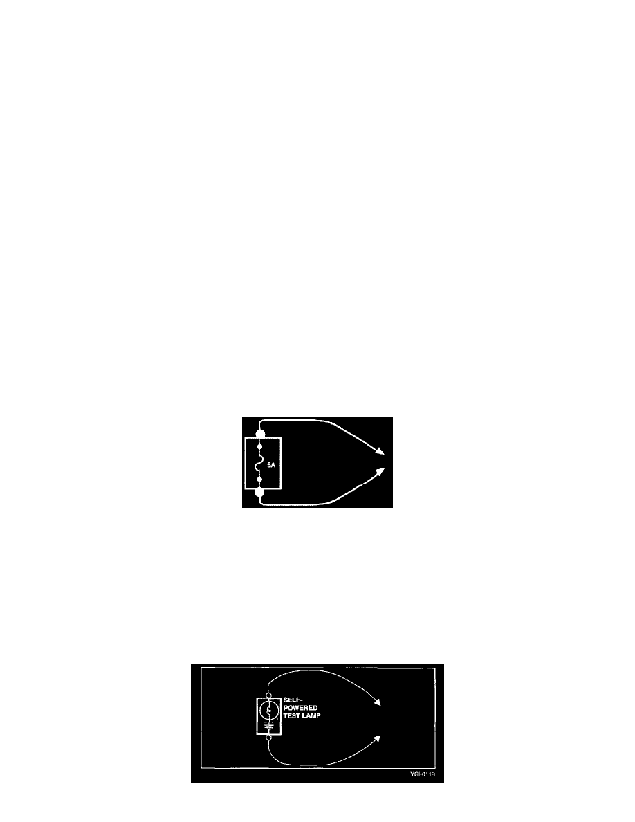
Jumper Wire With Fuse
Jumper Wire With Fuse
Use a jumper wire with fuse to by pass an open circuit. A jumper wire is made up of an in-line fuse holder connected to a set of test leads. This tool is
available with small clamp connectors providing adaption to most of the connectors without damage.
CAUTION
Do not use a fuse with a higher rating then the specified fuse that protests the circuit being tested. Do not use this tool in any situation to substitute for
input or output at the solid-state control module, such as electronic control module, transmission control module, etc.
Self-Powered Test Lamp and Ohmmeter