
Scoupe L4-1468cc 1.5L SOHC VIN J MFI (1994)
7.
Solder the crimp connector following the techniques listed under Soldering Techniques.
8.
Retape the connection using black electrical tape. Rewrap the wiring bundle with the original cover.
9.
Reinstall the wiring harness in its original position. Reattach the square ECM wiring loom cover to the intake manifold surge tank. Reconnect the
electrical connectors that were disconnected in steps 2 and 3 and replace the tie straps that were removed. Reconnect the battery ground cable.
10.
Verify that ail wiring harnesses are clear of moving parts or hot components.
11.
Clean off throttle body carbon deposits per procedure given in fuel system section of the appropriate shop manual. Clean TP sensor connectors at
throttle body by disconnecting and spraying with electrical contact cleaner.
12.
Using the M.U.T., set the idle speed and TP sensor voltage according to the procedures given in the fuel system section of the appropriate shop
manual.
SPECIFICATIONS:
TP Sensor = 480 - 520 mV
IDLE SPEED = 750 RPM
MP Sensor = 900 - 1000 mV
Service Procedure - Dong Hae
1.
Disconnect the battery ground cable.
2.
Under the crash pad on the driver's side, disconnect the ECM wiring harness connectors and ground wires from the ECM. Disconnect the two main
wiring harness connectors. Remove the tie-strap from around the ECM wiring harness and main wiring harness.
3.
In the engine compartment, disconnect the A/C low pressure switch connector, A/C compressor bullet connector (blue to red wire). distributor
connector, purge control solenoid valve connector, EGR control solenoid valve connector (California spec. vehicles only), pre-excitation resistor
connector, and the ground wires leading to the firewall (G07 for Excel, G06 for Scoupe). Remove the three bolts attaching the square ECM wiring
loom cover to the intake manifold surge tank. Remove the tie strap holding the EGR/purge control solenoid valve wifing to the accelerator cable.
4.
Pull the ECM wifing harness grommet out of the firewall and pull approximately 6 inches of the wiring harness into the engine compartment.
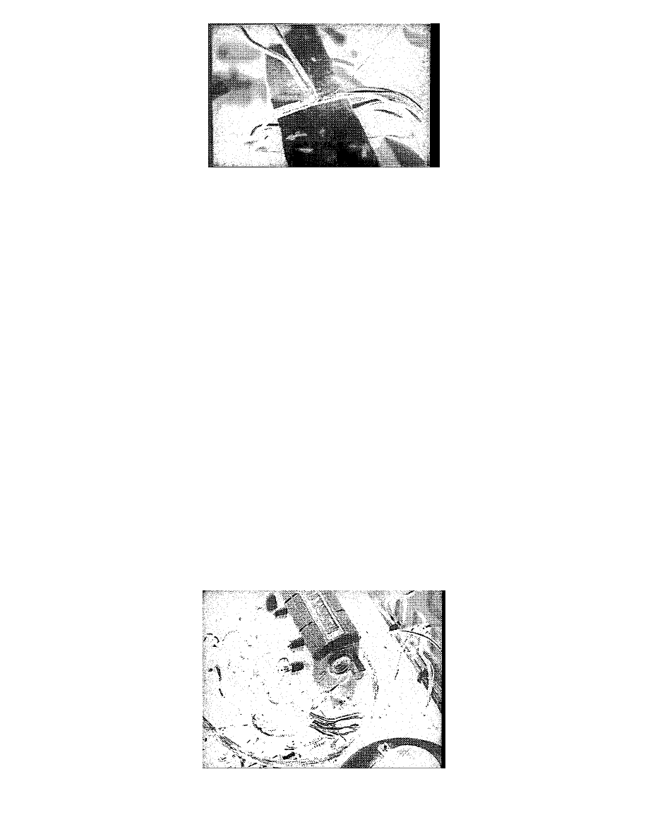
5.
The TP Sensor crimp connector splice is between the square ECM wiring loom cover and the firewall grommet. Carefully slice the tape that is
wrapped around the corrugate plastic wiring conduit and open up the conduit to expose the splice.