
Sonata V6-3.0L (1991)
ECU System
1.
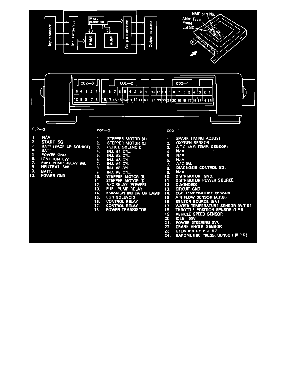
Connect a voltmeter between pin #19 of ECU connector C02-1, and ground.
NOTE: To test pins do not remove the connector from the ECU, instead insert a straight pin or needle from the back side of the connector to access the
pin.
2.
Turn the ignition switch to the "on" position, without starting the engine.
3.
Raise one drive wheel off the ground and manually rotate the wheel slowly.
4.
Observe the voltmeter, the voltage should oscillate between a positive voltage and 0 volts, as the wheel is rotated. If this occurs the Vehicle Speed
Sensor system is operating properly.
5.
If the voltmeter remains steady at reference voltage, there is either an open circuit between the VSS and the ECU, or the VSS is faulty. Before
replacing the VSS investigate the possibility of an open circuit in the VSS or instrument cluster grounds.
6.
If the voltmeter remains steady at 0 volts, there is either no reference voltage from the ECU, a ground between the ECU and the VSS, or the VSS is
faulty.
7.
To determine if the VSS is grounded or faulty, turn the ignition switch "off" and test for continuity between pin #19 of ECU connector C02-1, and
ground (using the same test method as in step #3). If continuity alternates, the VSS is operating properly (the ECU is faulty). If continuity remains
constant, either there is a ground between the VSS and the ECU, or the VSS is faulty.