
Sonata V6-3.3L (2006)
Wheel Speed Sensor: Initial Inspection and Diagnostic Overview
This article has been updated by technical service bulletin (TSB) 05-50-008 dated August 2005.
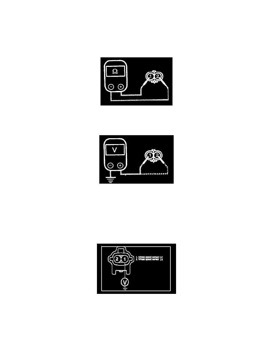
The 2006 Sonata Shop Manual (page BR-79) contains incorrect information for the wheel speed sensor power supply circuit inspection diagram.
The correct terminal is terminal 1.
Terminal 2 is the signal wire.
Inspection
1. Connect an ohmmeter between the wheel speed sensor terminals and measure the resistance.
Service standard
Front: 1,240 - 1,460 Ohms
Rear: 1,240 - 1,460 Ohms
2. Connect a voltmeter between the wheel speed sensor terminals, and measure the voltage by turning the wheel.
Note: Set the voltmeter to measure AC voltage.
Service standard: AC voltage detected.
Power Supply Circuit Inspection:
1. Turn ignition "ON" & engine "OFF".
2. Measure voltage between terminal "1" of the vehicle harness wheel speed sensor harness connector and chassis ground.
3. Specification: approx. B+
Note:
-
Voltage to terminal 1 will be approximately zero if a DTC code is set for the wheel speed sensor being tested.
-
The voltage between terminal 2 and chassis ground will fluctuate between a high of 0.89 ~ 1.26V and a low of 0.44 ~ 0.63V.