
Sonata GL V6-3.0L (1997)
1. Connect one lead of a test lamp or voltmeter to a ground. If you are using a voltmeter, be sure it is the voltmeter's negative lead test you have
connected to ground.
2. Connect the other lead of the test lamp or voltmeter to a selected test point (connector or terminal).
3. If the test lamp glows, there is voltage present. If you are using a voltmeter, note the voltage reading. A loss of more than 1 volt from
specifications indicates a problem.
Troubleshooting Equipment
Short finder is available to locate short to a ground. The short finder creates a pulsing magnetic field in the shorted circuit and shows you the location of
the short through body trim or sheet metal.
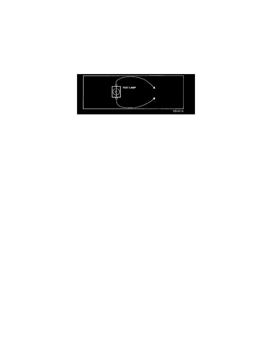
Voltmeter and Test Lamp
Use a test lamp or a voltmeter on circuits without solid-state units and use a test lamp to check for voltage. A test lamp is made up of 12 volt bulb with a
pair of leads attached. After grounding one lead, touch the other lead to various points along the circuit where voltage should be present. When the bulb
goes ON, there is voltage at the point being tested.
CAUTION
A number of circuits include solid-state modules such as engine control module used with computer command control injection. Voltage in these circuits
should be tested only with a 10 Mega Ohm or higher impedance digital voltmeter. Never use a test lamp on circuits that contain solid-state units.
Damage to the units may result.
A voltmeter can be used in place of a test lamp. While a test lamp shows whether the voltage is present or not, a voltmeter indicates how much voltage is
present.