
Sonata GLS V6-2.5L (2000)
CAUTION: Never use a self-powered test lamp on circuits that contain solid state modules. Damage to these modules may result.
An ohmmeter can be used in place of a self-powered test lamp. The ohmmeter shows how much resistance there is between two points along a circuit.
Low resistance means good continuity.
Circuits which include any solid-state devices should be tested only with a 10-megaohm or higher impedance digital multimeter. When measuring
resistance with a digital multimeter, the battery negative terminal should be disconnected. Otherwise, there may incorrect readings. Diodes and
solid-state devices in a be circuit can make an ohmmeter give a false reading. To find out if a component is affecting a measurement, take one reading,
reverse the leads and take a second reading. If different the solid-state device is affecting the measurement.
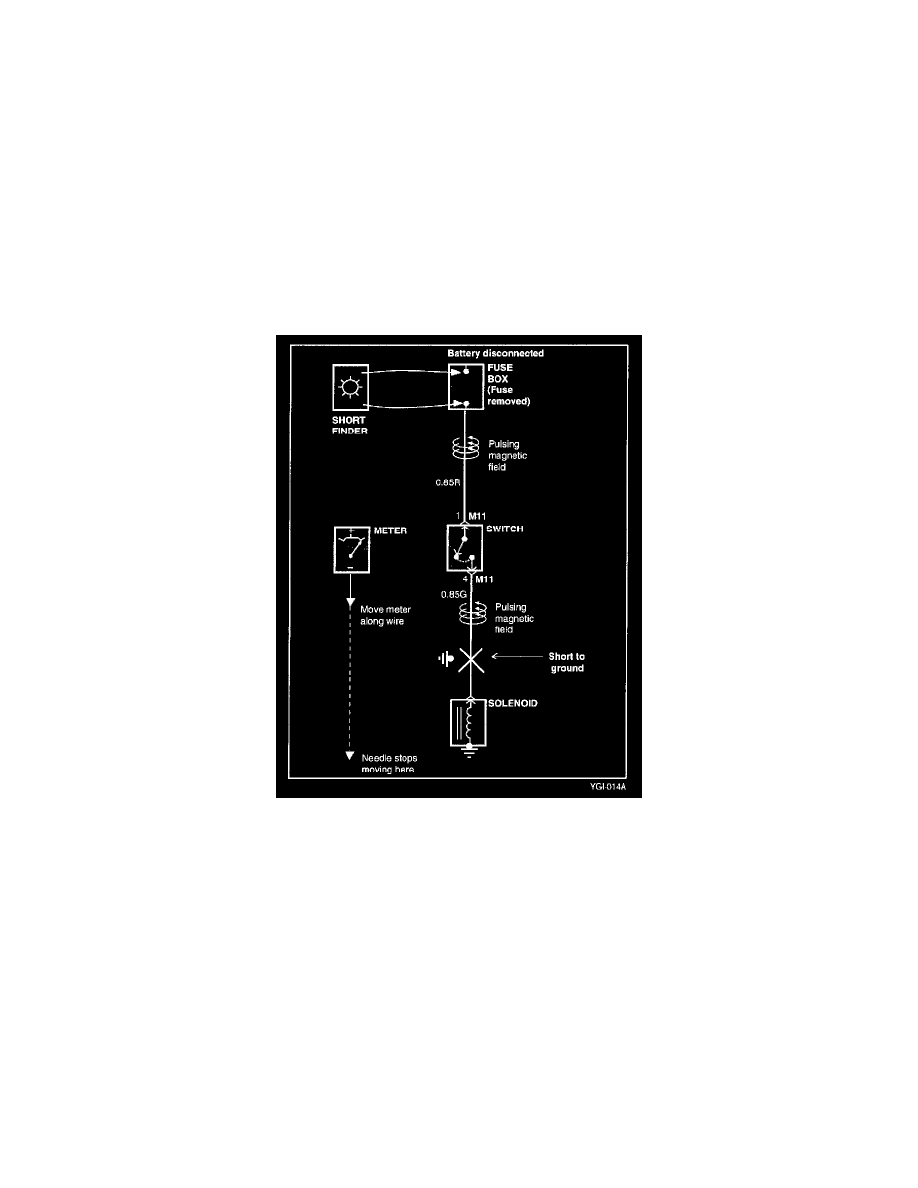
Short Finder
A short finder is available to locate a short to ground. The short finder creates a pulsing magnetic field in the shorted circuit and shows you the location
of the short through body trim or sheet metal.
Testing For A Short With A Short Finder
1. Remove the blown fuse. Leave the battery connected.
2. Connect the short finder across the fuse terminals.
3. Close all switches in series in the circuit that are being testing.
4. Turn on the short circuit locator. It sends pulses of current to the short. This creates a pulsing magnetic field around the wiring between the fuse
box and the short.
5. Beginning at the fuse box, slowly move the short finder along the circuit wiring. The meter will show current pulses through sheet metal and body
trim. As long as the meter is between the fuse and the short, the needle will move with each current pulse. Once the meter is moved past the point
of the short, the needle will stop moving. Check around this area to locate the cause of the short circuit.
Testing For Continuity