
Tiburon L4-1.8L (1997)
3. Drive out the lock pin with a punch inserted in hole "A."
4. Remove the pinion shaft, pinion gears and washers.
5. Remove the side gears and spacers. Do not mix the gears and spacers between the left and right sides.
ASSEMBLY
1. With the spacers installed on the back of the differential side gears, install the gears into the differential case. If reusing parts, install them in the
original positions noted during disassembly. If using new differential side gears, install medium thickness spacers 1.0 mm (0.039 inch).
2. Install washers on the back of the pinion gears. Install gears into the differential case, then insert the pinion shaft.
3. Measure the backlash between the side gear and the pinion gear. Backlash should be 0.025-0.150 mm (0.010-0.059 inch) and the right and left
hand gear pairs should have equal backlash. If the backlash is out of specification, disassemble and reassemble using different spacers that give the
correct backlash.
Standard value: 0.025L-0.150L mm (0.010-0.059 inch).
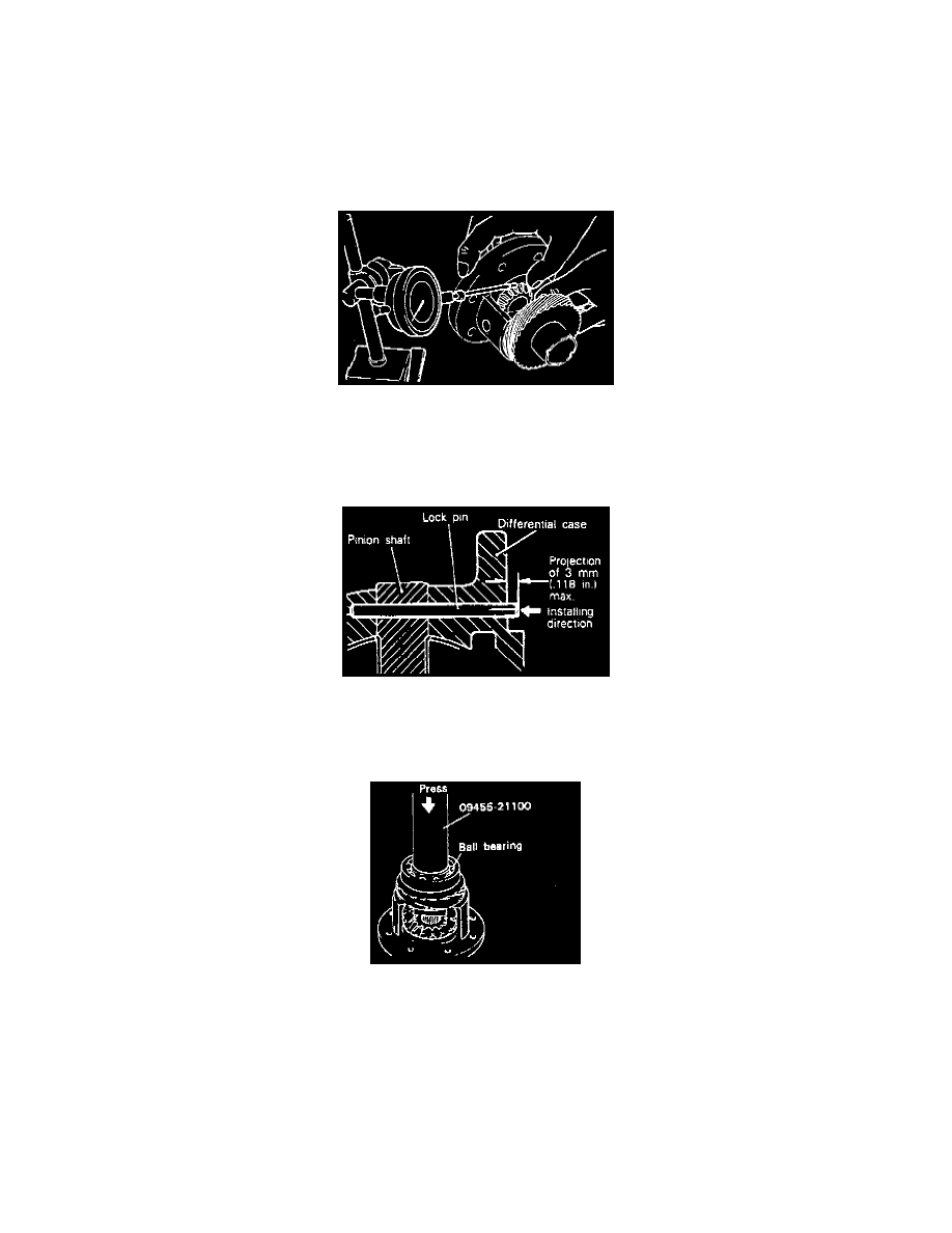
4. Install a new pinion shaft lock pin in the direction specified in the illustration. After installation, check that the projection is less than 3 mm (0.118
inch).
CAUTION: The lock pin must not be reused.
5. Press the bearings onto both ends of the differential case. Press on the inner race when installing the bearings. Do not apply load to outer race.
6. Install the differential drive gear onto the case.