
Tiburon L4-2.0L (1999)
Camshaft Position Sensor: Diagnostic Aids
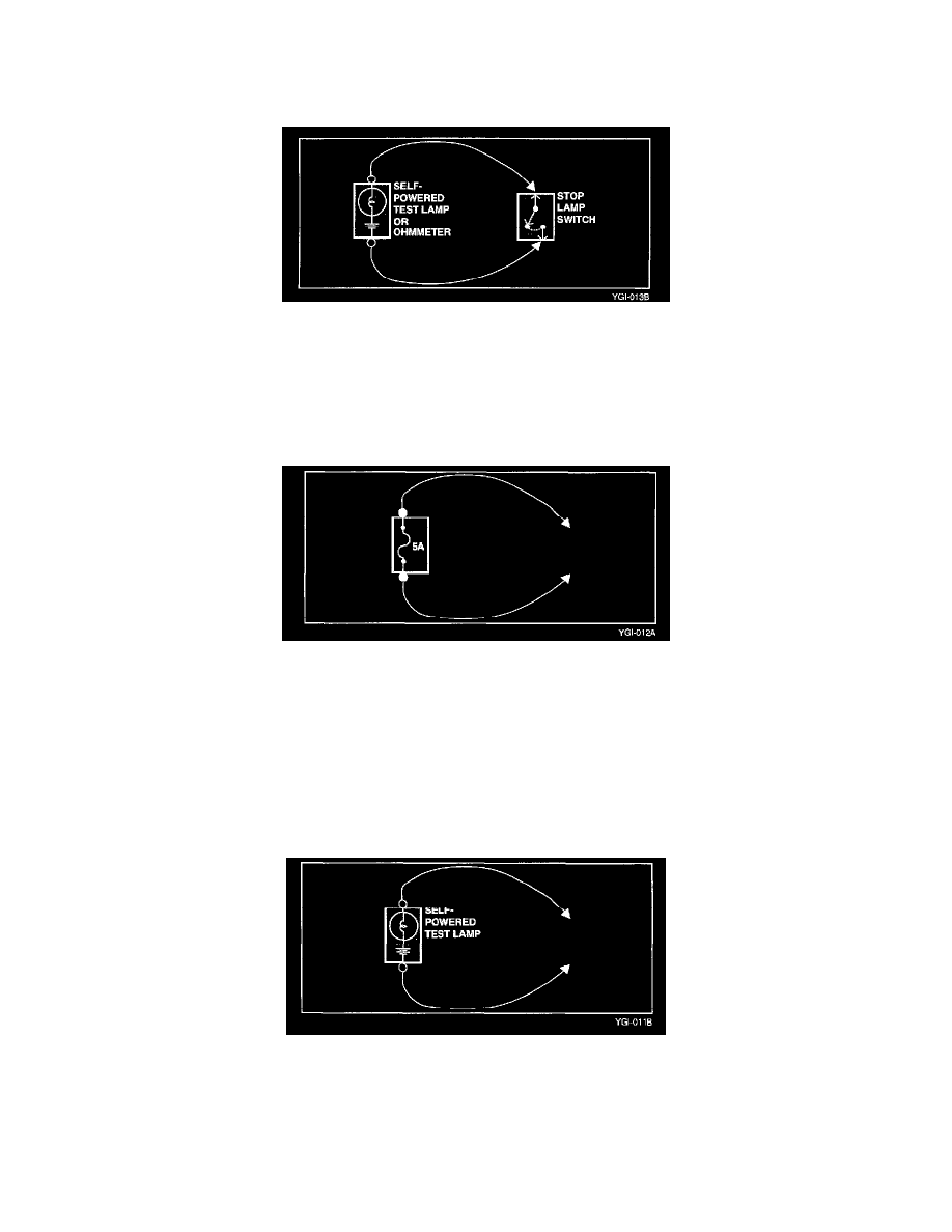
Continuity and Voltage Test
1. Disconnect the battery negative terminal.
2. Connect one lead of a self powered test lamp or ohmmeter to one end of the part of the circuit you wish to test. If you are using an ohmmeter, hold
the leads together and adjust the ohmmeter to read zero Ohms.
3. Connect the other lead to the other end.
4. If the self-powered test lamp glows, there is continuity. If you are using an ohmmeter, low or zero resistance means good continuity.
Jumper Wire With Fuse
Use a jumper wire with fuse to by pass an open circuit.
A jumper wire is made up of an in-line fuse holder connected to a set of test leads. This tool is available with small clamp connectors providing adoption
to most of the connectors without damage.
CAUTION
Do not use a fuse with a higher rating than the specified fuse that protests the circuit being tested. Do not use this tool in any situation to substitute for
input or output at the solid-state control module, such as ECM, TCM, etc.
Self-Powered Test Lamp and Ohmmeter
Use a self powered test lamp or a ohmmeter to check for continuity. Self-powered test lamp is made of a bulb, battery and two leads are touched
together, the lamp will go on. Prior to checking the points, first disconnect the battery ground cable or remove the fuse which feeds the circuit you are
working on.
CAUTION:
Never use a self-powered test lamp on circuits that contain solid state modules. Damage to these units may result.