
Tiburon L4-2.0L (1999)
An ohmmeter can be used in place of a self-powered test lamp. The ohmmeter shows how much resistance there is between two points along a circuit.
Low resistance means good continuity.
Circuits which include any solid-state devices should be tested only with at 10 Mega Ohm or higher impedance digital multimeter. When measuring
resistance with a digital multimeter, battery negative terminal should be disconnected. Otherwise, there may be incorrect readings. Diodes and solid-state
devices in a circuit can make an ohmmeter give a false reading. To find out if a component is affecting a measurement, take one reading, reverse the
leads and take a second reading. If the readings differ, the solid-state device is affecting the measurement.
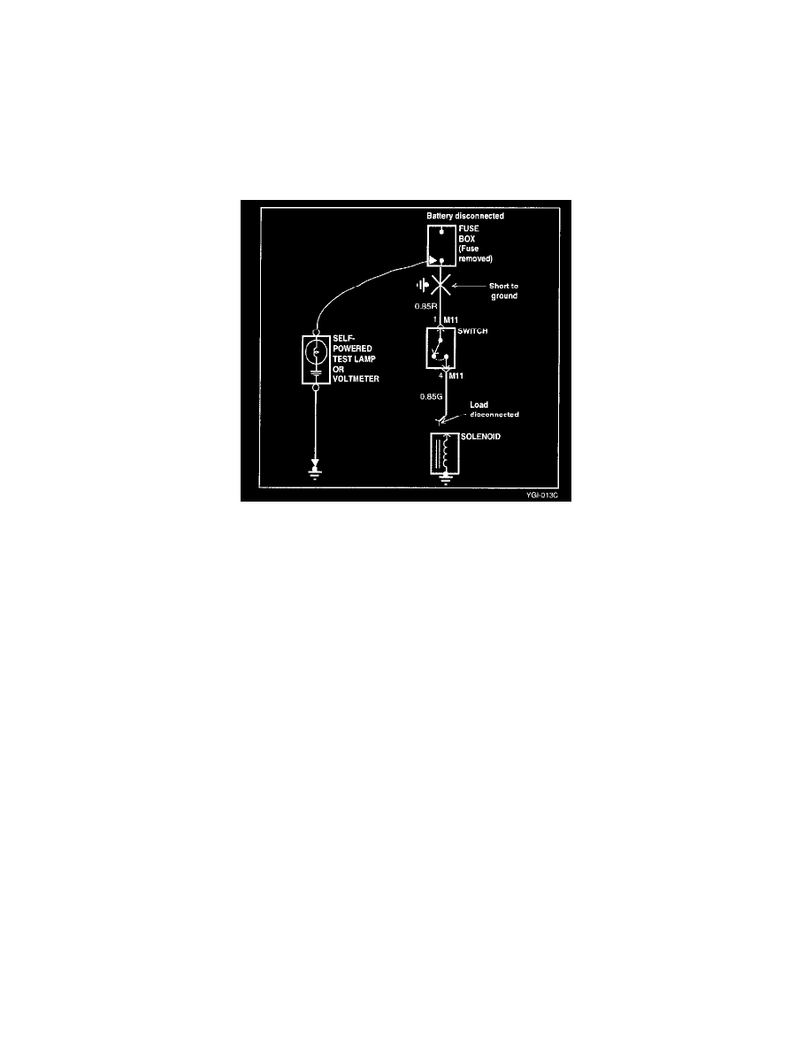
Testing For Short to Ground
1. Disconnect the battery negative terminal.
2. Connect one lead of a self powered test lamp or an ohmmeter to the fuse terminal on the load side.
3. Connect the other lead to a ground.
4. Beginning near the fuse block move the harness from side to side. Continue this point (about six inches apart) while watching the self powered test
lamp or ohmmeter.
5. When the self powered test lamp glows, or ohmmeter registers, there is a short to a ground in the wiring near that point.
Testing For Short to Power