
Tucson AWD L4-2.0L (2007)
Mode Check
Error Diagnostics
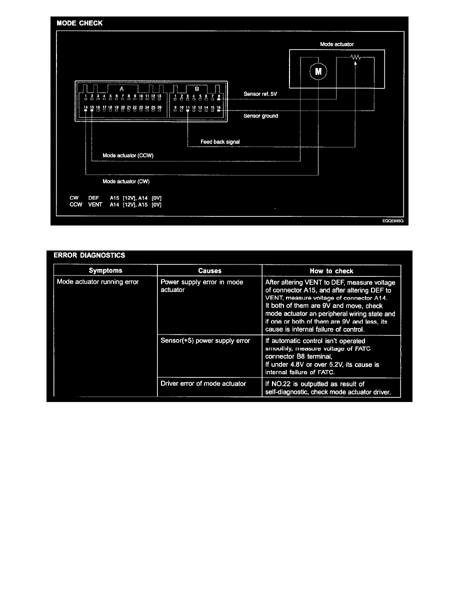
MODE CHECK
In turning on IG and selecting mode switch, sequential operation begins in order of Vent -> Bi-level -> Blower -> Mix. DIP mode works regardless of
order at selecting it. As shown in the above figure, in adjusting mode switch from VENT to DEF, 12 V is outputted from connector B4, 0 V is supplied
for B5 and mode motor works in direction of DEF. In adjusting mode switch from DEF to VENT, 12 V is outputted from connector B5, 0 V is supplied
for B4 and mode motor works in direction of VENT. When mode actuator has to move to a certain location for its automatic control, mode feedback
signal terminal moves equally in mode actuator and informs controller of location of mode actuator through mode connector B6. Comparing original
value with the inputted value, it works until they are same.
Sensor Check