
Ascender 2WD V8-5.3L (2004)
6. Install the rear electrical center cover.
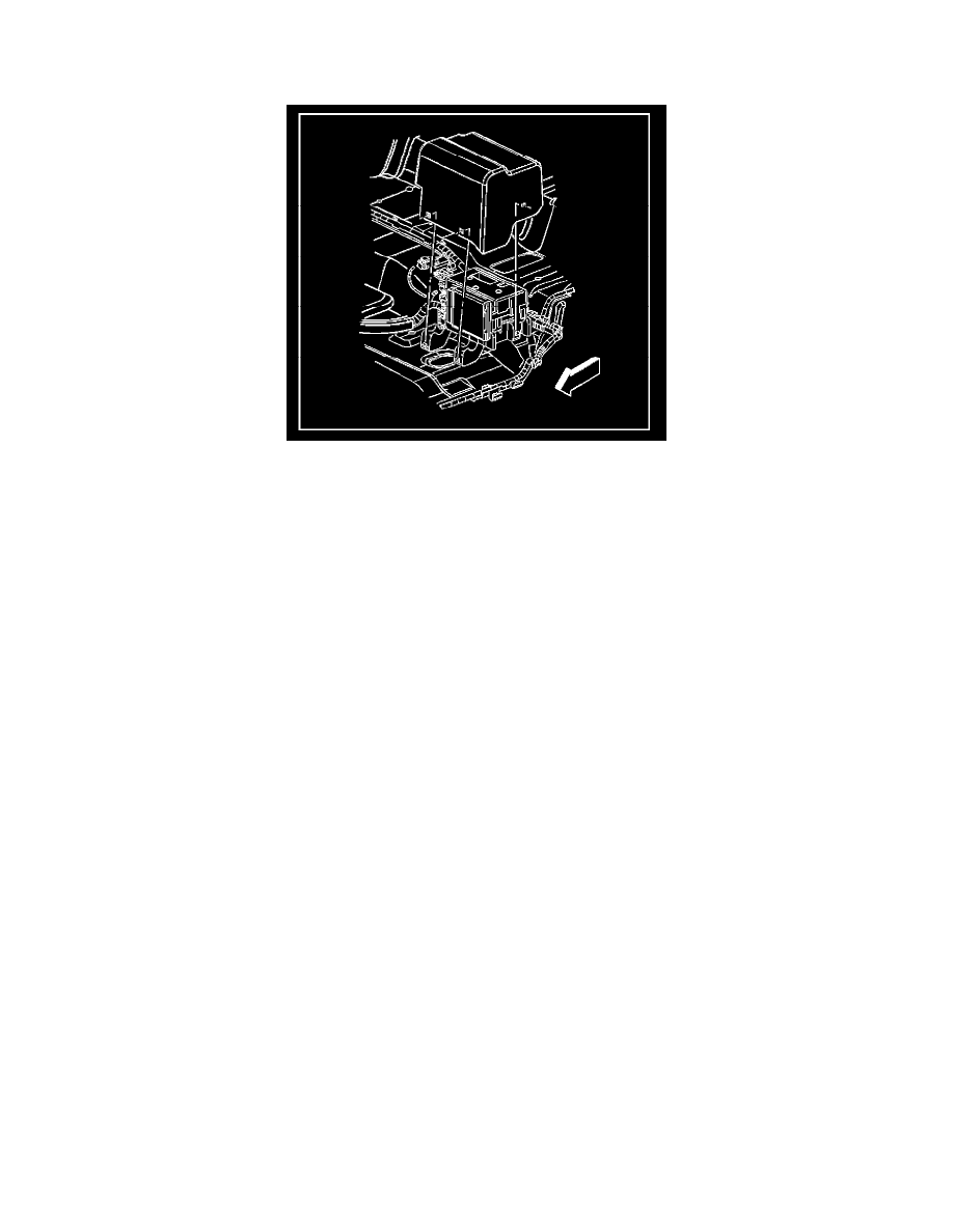
7. Install the left second row seat.
8. Connect the negative battery cable.
BCM Programming/RPO Configuration
Body Control Module (BCM) Programming/RPO Configuration
Introduction
The procedures below are designed to set-up the body control module (BCM) correctly during BCM related service. Before you start, read these
procedures carefully and completely.
Important: The following procedures must be followed:
1. Read this procedure carefully and completely.
2. The BCM will not function properly if the Setup New BCM procedure is not performed.
3. Perform the Programming Theft Deterrent System Components in Theft Deterrent after successfully finishing the Setup New BCM procedure. If
the Programming Theft Deterrent System Components in the Theft Deterrent procedure is not performed after a BCM replacement, one of the
following conditions will occur:
-
The vehicle will not be protected against theft by the PASSLOCK system.
-
The engine will not crank nor start.
Setup New Body Control Module (BCM)
Important: After the procedure is completed, the personalization settings of the BCM are set to a default setting. Inform the customer that the
personalization must be set again.
Refer to Service Programming System (SPS) (Remote Procedure) or Service Programming System (SPS) (Pass-Thru Procedure) or Service
Programming System (SPS) (Off Board Remote Procedure) or Service Programming System (SPS) (Off Board Pass-Thru Procedure) in Programming.
Important: After programming, perform the following to avoid future misdiagnosis:
1. Turn the ignition OFF for 10 seconds.
2. Connect the scan tool to the data link connector.
3. Turn the ignition ON with the engine OFF.
4. Use the scan tool in order to retrieve history DTCs from all modules.
5. Clear all history DTCs.
Service Programming System (SPS) Description
Service Programming System (SPS) Description
The service programming system (SPS) allows a technician to program a control module through the data link connector (DLC). The information
transfer circuit that is used at the DLC is the same serial data circuit used by the scan tool for retrieving diagnostic trouble codes (DTCs), displaying
data, clearing DTCs, etc. This procedure offers the ability to install software/calibrations matched to a particular vehicle.