
Ascender 4WD V8-5.3L (2004)
Body Control Module Replacement
Removal Procedure
Important: The ignition switch should be in the OFF position when connecting or disconnecting the connectors to the body control module (BCM).
Always disconnect the 40-way flex BCM electrical connector FIRST, the 32-way tan connector SECOND and the 24-way gray electrical
connector LAST.
Always connect the 24-way gray electrical connector FIRST, the 32-way tan connector SECOND and the 40-way flex electrical connector
LAST.
The BCM can set DTCs with the ignition switch in the OFF position. The BCM has battery run down protection for the courtesy lamp
circuit. The BCM battery run down protection cannot detect shorts on inputs or other circuits which the BCM does not control. Use the
scan tool in order to activate the POWER DOWN NOW mode. Use the POWER DOWN NOW mode in order to check for current draws
on circuits that are not controlled by the BCM, or controlled by the battery run down protection system.
Do not touch the exposed electrical contacts of the flex connector. Do not open the BCM housing. The module does not have any
serviceable components. The module may be replaced only as an assembly.
1. Disconnect the negative battery cable.
2. Remove the left second row seat.
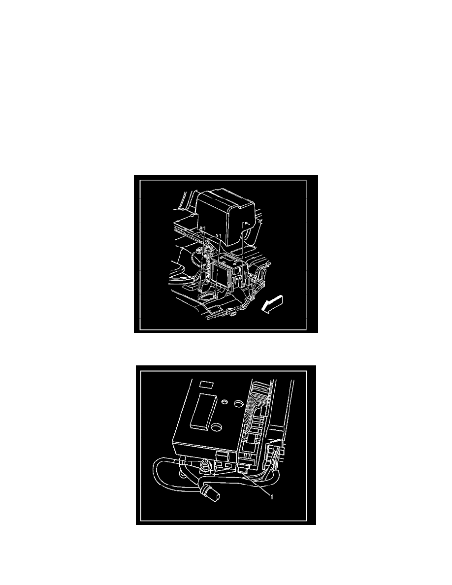
3. Remove the rear electrical center cover.
4. Press down and hold the locking tab (1) that retains the sliding latch.
5. Disengauge the sliding latch retaining the BCM to the rear electrical center, by sliding the latch inboard approximately 40 mm (1.6 in).