
Axiom 2WD V6-3.5L (2002)
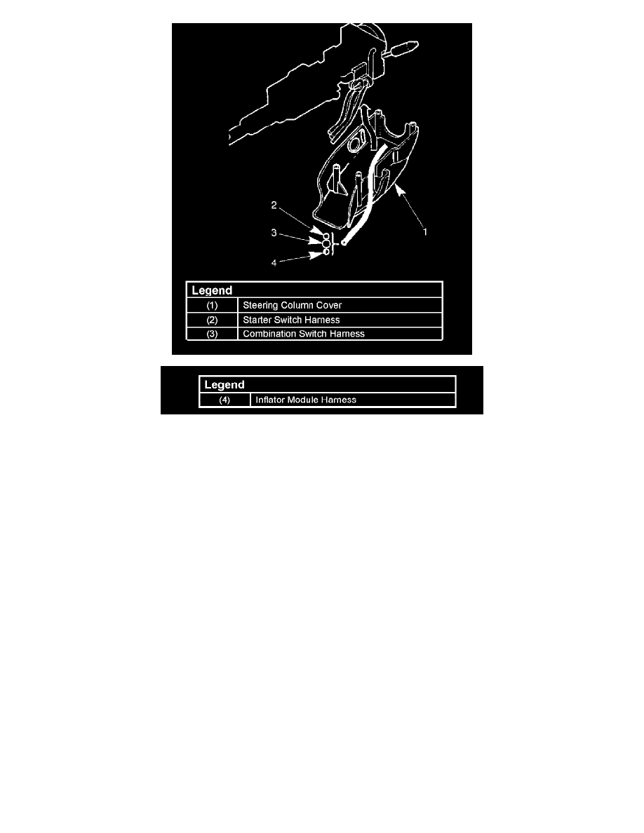
7. When installing the steering column cover, be sure to wire (through each harness) as illustrated so that the harnesses starter switch, combination
switch and SRS coil may not catch wiring.
8. Install steering wheel by aligning the setting marks made during removal.
Caution: Never apply force to the steering wheel shaft a hammer or other impact tools in an attempt to remove the steering wheel. The steering
shaft is designed as an energy absorbing unit.
9. Tighten the steering wheel fixing nut to the specified torque.
Torque: 34 Nm (25 ft. lbs.)
10. Support inflator module and carefully connect the SRS connector and horn lead, then install inflator module.
Note: Pass the lead wire through the tabs on the plastic cover (wire protector) of inflator to prevent lead wire from being pinched.
11. Tighten fixing bolts to specified torque.
Torque: 9 Nm (78 inch lbs.)
12. Install driver knee bolster (reinforcement).
13. Install instrument panel lower cover, then install the engine hood opening lever.
14. Connect the yellow 2-way SRS connector located under the steering column.
15. Connect the battery ground cable.
System Inspection
Turn the ignition switch to the "ON" position and observe the warning lamp. The SRS lamp should flash 7 times. If the lamp does not operate
correctly, refer to Restraint Systems.