
Hombre L4-2.2L CPC (1996)
Step 1: Cut off terminal between core and insulation crimp (minimize wire loss) and remove seal for Weather Pack(R) terminals.
Step 2: Apply correct seal per gauge size of wire and slide back along wire to enable insulation removal (Weather Pack(R) terminals only).
Step 3: Remove insulation.
Step 4: Align seal with end of cable insulation (Weather Pack(R) terminals only).
Step 5: Position strip (and seal for Weather Pack(R)) in terminal.
Step 6: Hand crimp core wings.
Step 7: Hand crimp insulation wings (non-Weather Pack(R)). Hand crimp insulation wings around seal and cable (Weather Pack(R)).
Step 8: Solder all hand crimped terminals.
Diode Replacement
Many vehicle electrical systems use a diode to isolate circuits and protect the components from voltage spikes. When installing a new diode, use the
following procedure:
Step 1: Open the Harness
If the diode is taped to the harness, remove all of the tape.
Step 2: Remove inoperative Diode
Paying attention to current flow direction, remove inoperative diode from the harness with a suitable soldering tool. If the diode is located next to a
connector terminal, remove the terminal(s) from the connector to prevent damage from the soldering tool.
Step 3: Strip the Insulation
Carefully strip away a section of insulation next to the old soldered portion of the wire(s). Do not remove any more than is needed to attach the
new diode.
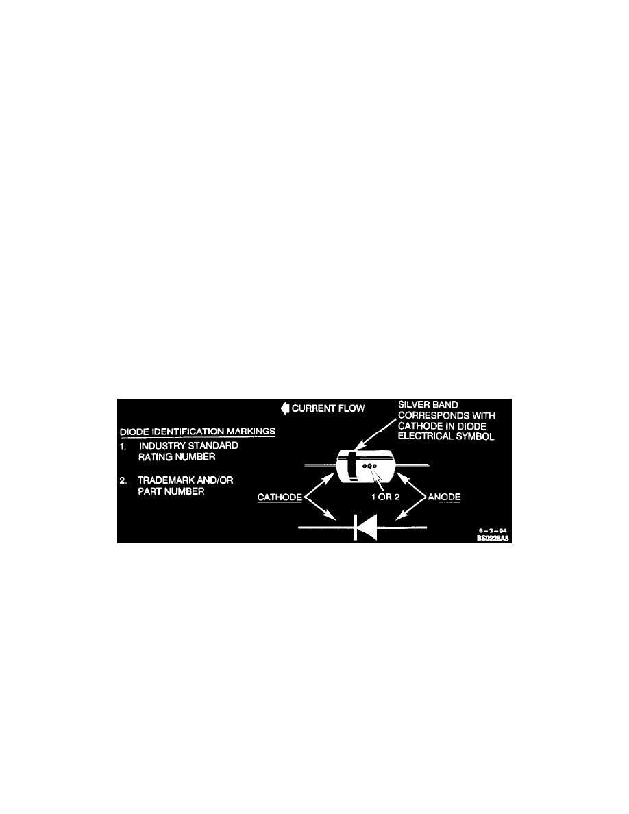
Diode Identification
Step 4: Install New Diode
Check current flow direction of the new diode, being sure to install the diode with correct bias. Refer the image for replacement diode symbols and
current flow explanations. Attach the new diode to the wire(s) using 60/40 rosin core solder. Use a beat sink (aluminum alligator clip) attached
across the diode wire ends to protect the diode from excess heat. Follow the manufacturer's instructions for the soldering equipment you are using.
Step 5: Install Terminal(s)
Install terminal(s) into the connector body if previously removed in Step 2.
Step 6: Tape Diode to Harness
Tape the diode to the harness or connector using electrical tape. To prevent shorts to ground and water intrusion, completely cover all exposed
wire and diode attachment points.
In the event 1 Amp, 50 PIV (Peak Inverse Rating) diodes are unavailable, a universal diode with a 1 Amp, 400 PIV rating can be used for the
following applications:
^
A/C Compressor Clutch
^
ABS/4WAL (the ABS Diode on the Delco Moraine is hidden inside of an electrical connector under the carpet at the RH panel)
^
Wiper
^
Charging System (hidden in wire harness)