
Hombre L4-2.2L CPC (1996)
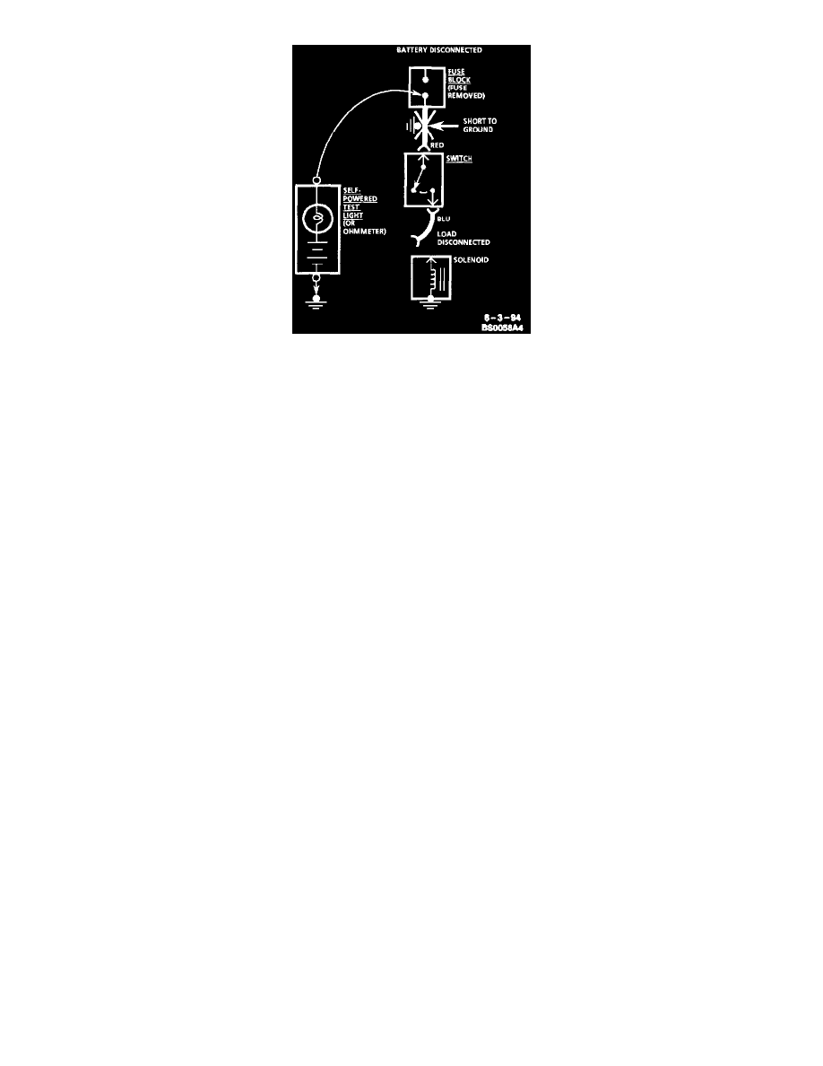
Testing For Short With Self-Powered Test Light Or Ohmmeter
WITH A SELF-POWERED TEST LIGHT OR OHMMETER.
1. Remove the blown fuse and disconnect the Battery and load.
2. Connect one lead of a self-powered test light or ohmmeter to the fuse terminal on the load side.
3. Connect the other lead to a known good ground.
4. Beginning near the Fuse Block, wiggle the harness from side to side. Continue this at convenient points (about 6 Inches apart) while watching the
self-powered test light or ohmmeter.
5. When the self-powered test light glows, or the ohmmeter registers, there is a short to ground in the wiring near that point.
FUSES POWERING SEVERAL LOADS
1. Find the schematic under "Fuse Block Details" for the fuse that has blown.
2. Open the first connector or switch leading from the fuse to each load.
3. Replace the fuse.
^
If the fuse blows, the short is in the wiring leading to the first connector or switch. Use a test light or DVM as described.
^
If fuse does not blow, refer to next step.
4. Close each connector or switch until the fuse blows in order to find which circuit has the short. Connect test lamp or meter at the connector to the
suspect circuit (disconnected) rather than at the fuse terminals.
Intermittent and Poor Connections
Most intermittents are caused by faulty electrical connections or wiring, although occasionally a sticking relay or solenoid can be a problem. Some items
to check are:
^
Poor mating of connector halves, or terminals not fully seated in the connector body (backed out).
^
Dirt or corrosion on the terminals. The terminals must be clean and free of any foreign material which could impede proper terminal contact.
^
Damaged connector body, exposing the terminals to moisture and dirt, as well as not maintaining proper terminal orientation with the component
or mating connector.
^
Improperly formed or damaged terminals. All connector terminals in problem circuits should be checked carefully to ensure good contact tension.
Use a corresponding mating terminal to check for proper tension. Refer to Checking Terminal Contact for the specific procedure.
^
The J 35616-A Connector Test Adapter Kit must be used whenever a diagnostic procedure requests checking or probing a terminal. Using the
adapter will ensure that no damage to the terminal will occur, as well as giving an idea of whether contact tension is sufficient. If contact tension
seems incorrect, refer to Checking Terminal Contact.
^
Poor terminal-to-wire connection. Some conditions which fall under this description are poor crimps, poor solder joints, crimping over wire
insulation rather than the wire itself, corrosion in the wire-to-terminal contact area, etc.
^
Wire insulation which is rubbed through, causing an intermittent short as the bare area touches other wiring or parts of the vehicle.
^
Wiring broken inside the insulation. This condition could cause a continuity check to show a good circuit, but if only 1 or 2 strands of a
multi-strand type wire are intact, resistance could be far too high.
To avoid any of the above problems when making wiring or terminal repairs, always follow the instructions for wiring and terminal repair outlined under
the Wire Repair Procedures.
Checking Terminal Contact
DESCRIPTION
When diagnosing an electrical system that utilizes Metri-Pack 150/280/480/630 series terminals (refer to Terminal Repair Kit, J 38125-A, J
38125-4 for terminal identification), it is important to check terminal contact between a connector and component, or between in-line connectors,
before replacing a suspect component.