
Hombre S Regular Cab 2WD L4-2.2L CPC (1998)
3. Install pulley rotor and bearing puller guide J 33023-A to the front head and install 3 41552 pulley rotor and bearing puller down into the inner
circle of slots in the rotor. Turn the J 41552 puller clockwise in the slots in the rotor.
4. Hold the J 41552 puller in place and tighten the puller screw against the puller guide to remove the pulley rotor and bearing assembly.
Install or Connect
1. With the compressor mounted to the J 34992 holding fixture, position the rotor and bearing assembly on the front head.
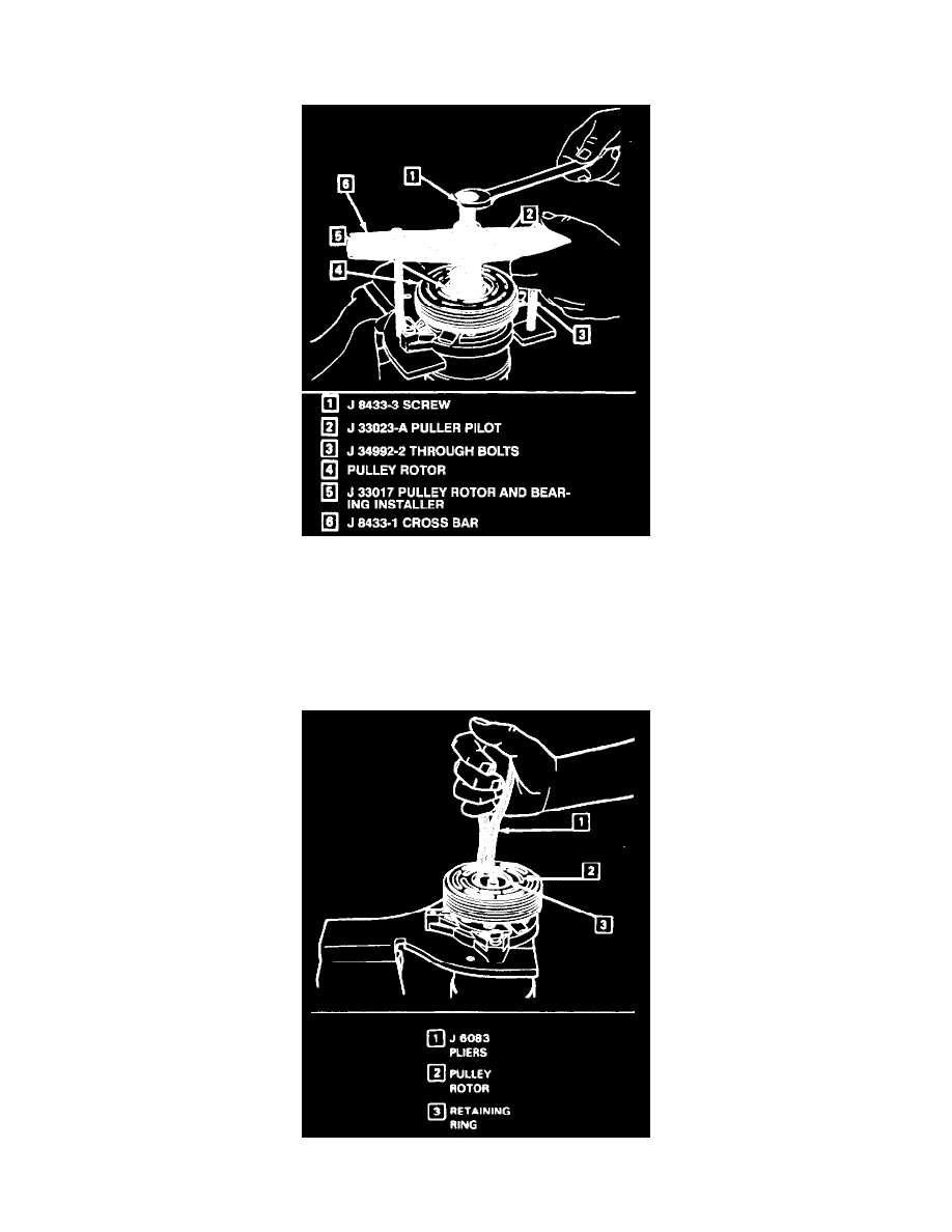
2. Position the J 33017 pulley, rotor and bearing installer and J 33023-A puller pilot directly over the inner race of the bearing.
3. Position puller crossbar J 8433-1 on the puller pilot J 33023-A and assemble the two J 34992 through bolts and washers through the puller bar
slots and thread them into the J 34992 holding fixture. The thread of the through bolts should engage the full thickness of the holding fixture.
4. Tighten the center screw in the J 8433-1 puller crossbar to force the pulley rotor and bearing assembly onto the compressor front head. Should the
J 33017 pulley rotor and bearing installer slip off direct in-line contact with the inner race of the bearing, loosen the J 8433-1 center forcing screw
and realign the installer and pilot so that the J 33017 installer will properly clear the front head.
5. Install rotor and bearing assembly retainer ring, using snap ring pliers J 6083.
6. Reinstall clutch plate and hub assembly as described previously.