
Hombre S Regular Cab 2WD L4-2.2L CPC (1998)
Control Assembly: Description and Operation
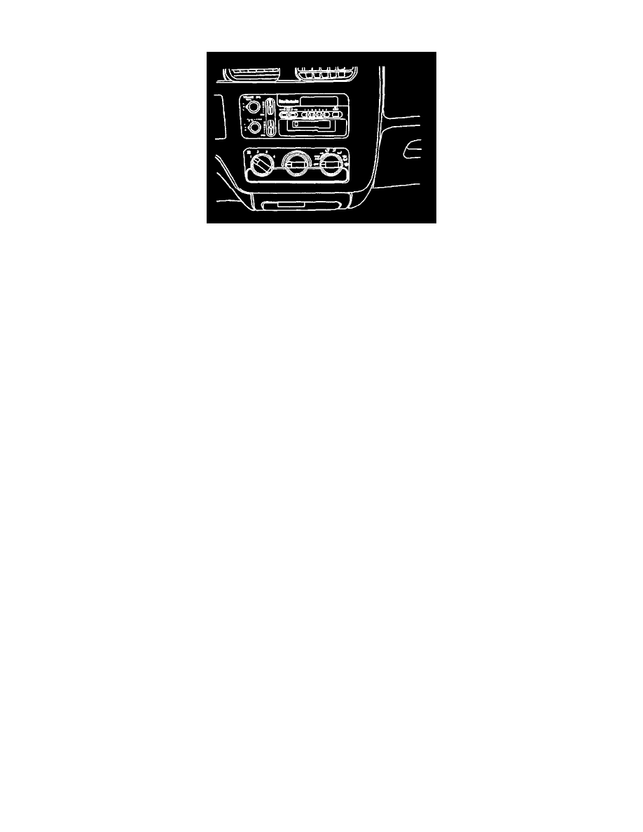
Control Assembly
The control assembly in the instrument panel contains three controls: a switch to control blower speed, one rotary knob to select the desired operating
mode and a second rotary knob to control air temperature.
The controls are lit when the headlamps are on. Voltage is provided by the instrument panel lighting circuit. The control assembly lamp is in parallel
with the instrument cluster bulbs, the radio dial bulb, and certain other interior illumination bulbs. Brightness of the dial illumination is controlled by the
dimmer control of the headlamp switch.
Temperature Control
The temperature door is controlled by an electric motor that positions the door based on the temperature knob location.
When the temperature control is in the Blue (Cold) position, the air delivered by the heater system is unheated. When the temperature control is in the
Red (Hot) position, all of the air passing through the heater module is heated before it is discharged. Intermediate positions of the temperature control
result in a mixture of heated and unheated air to provide more moderate air temperatures.
As the temperature control is moved away from the Blue (Cold) position, the temperature valve moves away from the heater core to allow some air to
flow through the heater core. The farther the temperature control is moved toward the Red (Hot) position, the more the temperature valve is turned away
from the entrance to the heater core and the greater the airflow through the heater core. Heating a greater portion of the total airflow in this manner
results in a warmer discharge of air from the outlets.
When the temperature control is in the full Red (Hot) position, the temperature valve blocks off the passage that allows air to bypass the heater core and
causes all of the airflow to go through the heater core for maximum heating. This method of temperature control provides a very rapid response to any
change in temperature selection throughout the entire range when the engine is warmed up.
Mode Control
The mode rotary control knob operates a rotary vacuum switch that routes engine vacuum to specific hoses in the vacuum harness. These hoses control
various vacuum actuator's on the HVAC system. Each actuator operates an air valve (a door-like hinged deflector) that routes airflow to the various
outlets as indicated by the symbols on the face plate.
For additional information on mode operation. Refer to Mode Operation.
Blower Speed Control
The blower switch provides a choice of various blower speeds. The blower switch receives power through a fuse in the fuse block when the ignition is
ON. In the various speed positions, the circuit continues through the heater wiring harness to the blower motor resistor assembly near the blower motor.
From the resistor assembly, the circuit goes to the blower motor terminal to operate the blower motor.
The blower motor relay provides battery voltage to the blower motor assembly only during high blower motor assembly speed. The blower motor circuit
is completed to ground by a wire in the heater wiring harness. This wire goes from the blower motor terminal to a terminal at the dash panel sheet metal
near the blower assembly in the engine compartment.