
Hombre S Regular Cab 2WD L4-2.2L CPC (1998)
10. Inspect the brush springs for distortion or discoloring. If the springs are weak, bent, or discolored, replace the frame and field assembly.
11. Inspect the field coils.
-
Look for burned or damaged insulation, damaged connections or loose poles.
-
If the conditions of the coils is doubtful, replace the field and frame assembly.
12. Inspect the field coils for grounds.
-
Connect a self-powered test lamp between the field frame and the field connector. Make sure the brush ends do not contact the field frame.
-
If the test lamp lights, the field coils are grounded. Replace the field and frame assembly.
13. Inspect the field coils for opens.
-
Connect a self-powered lamp between the field connector and each of the brushes.
-
If the test lamp does not light at both brushes, the field coils are open. Replace the frame and field assembly
14. Inspect for field coils for shorts.
-
Shorts are indicated by poor motor performance after everything else has been checked out.
-
The coils cannot be replaced separately because of the integral frame construction. The frame and field assembly must be replaced.
15. Inspect the drive assembly (clutch) by turning the drive pinion in the cranking direction. If the drive pinion turns or slips in the cranking direction,
replace the over-running clutch assembly.
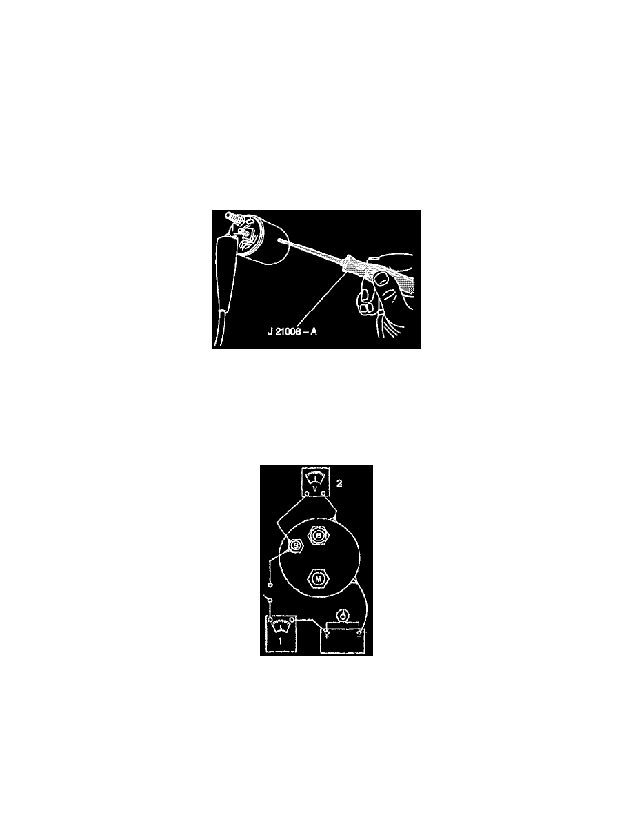
16. Inspect the solenoid for grounds using a self-powered 12 volt test lamp.
16.1. Connect the test lamp between the BAT terminal and the case. The lamp should not light (terminal should not be grounded).
16.2. Connect the test lamp between the S terminal and the case. Then connect the test lamp between the M terminal and the S terminal or between
the M terminal and the case. The lamp should turn on.
16.3. If the solenoid does not pass these checks, replace it.
NOTICE: To prevent overheating of the solenoid pull-in winding, do not leave the winding energized for more than 15 seconds. The current
draw will decrease as the winding temperature increases.
17. Inspect the hold-in winding and the pull-in winding.
17.1. If the solenoid is not removed from the starter motor, the field lead must be removed from the terminal on the solenoid before making these
tests.
17.2. To check both windings, connect an ammeter in series with a 12 volt battery and the switch terminal on the solenoid. Connect a carbon pile
across the battery. Ground the solenoid motor terminal. Adjust the voltage to 10 volts and note the ammeter reading. It should be 60 to 85
amperes.
17.3. Note the ampere reading. A high reading indicates a shorted or grounded winding, and a low reading indicates excessive resistance.
-
The resistance of the windings can be read directly using a digital ohmmeter that can measure tenths of an ohm.
-
Coil resistance can be determined by dividing the voltage by the current (amperes).