
Hombre S Space Cab 2WD V6-4.3L (2000)
Accessory Delay Module: Testing and Inspection
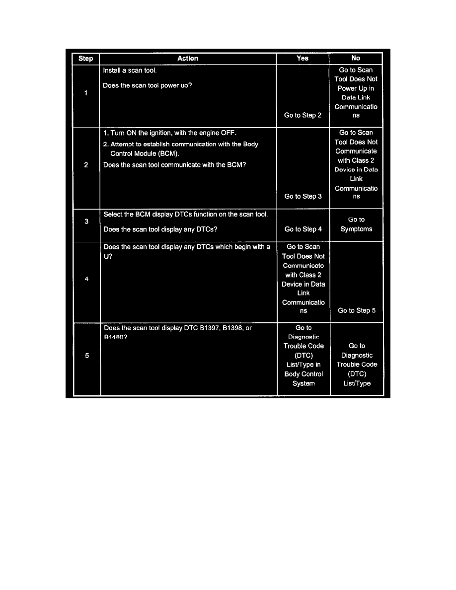
A Diagnostic System Check - Retained Accessory Power
Steps 1 - 5
Test Description
The number(s) below refer to the step number(s) on the diagnostic table.
2. Lack of communication may be due to a partial malfunction of the class 2 serial data circuit or due to a total malfunction of the class 2 serial data
circuit. The specified procedure will determine the particular condition.
3. This step will check for any DTCs that may be stored in the BCM. These DTCs should be addressed before proceeding to the symptoms list.
4. The presence of DTCs which begin with U indicate some other module is not communicating. The specified procedure will compile all the
available information before