
Hombre S Space Cab 2WD V6-4.3L (2000)
Hydraulic Control Assembly - Antilock Brakes: Service and Repair
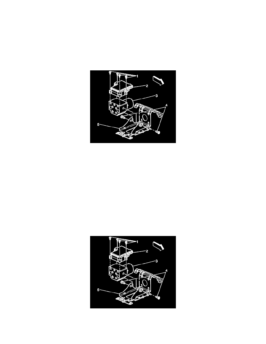
Removal Procedure
Important: Thoroughly wash all contaminants from around the EHCU. The area around the EHCU must be free from loose dirt to prevent
contamination of disassembled ABS components.
1. Disconnect the two electrical harness connectors from the EBCM (2).
Important: Make sure that brake lines are tagged and kept in order for proper reassembly.
2. Disconnect the 5 brake lines from the BPMV (3).
3. Remove 2 bolts (4) securing the BPMV mounting bracket (5) to the BPMV (3).
4. Disconnect the 2 way ABS pump motor connector.
5. Remove the four T-25 TORSO screws (1) from the EBCM (2).
Important: Do not use a tool to pry the EBCM or the BPMV. Excessive force will damage the EBCM.
6. Remove the EBCM (2) from the BPMV (3). Removal may require a light amount of force.
Important: Do not reuse the EBCM mounting bolts. Always install new bolts.
7. Clean the EBCM (2) to BPMV (3) mounting surfaces with a clean cloth.
Installation Procedure
Notice: Refer to Fastener Notice in Service Precautions.
Important: Do not use RTV or any other type of sea/ant on the EBCM gasket or mating surfaces.
1. Install EBCM (2) onto BPMV (3).
Important: Do not reuse the old mounting bolts. Always install new bolts with the new BPMV.