
Hombre S Space Cab 2WD V6-4.3L (2000)
-
Turn ON the engine.
-
Turn ON the circuit and/or system with a scan tool in Output Controls.
-
Turn ON the switch for the circuit and/or system being tested.
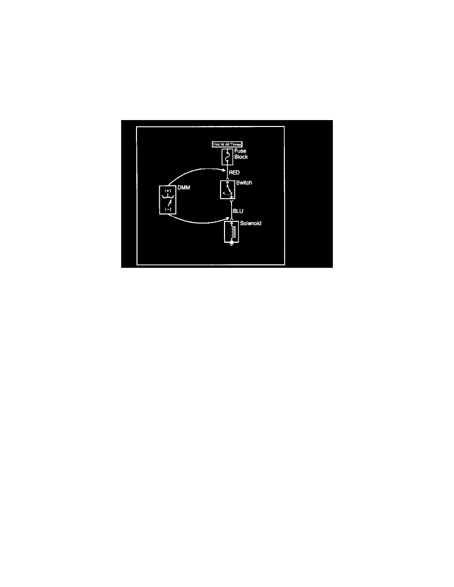
3. Select the V (AC) or V (DC) position on the DMM.
4. Connect the positive lead of the DMM to the point of the circuit to be tested.
5. Connect the negative lead of the DMM to a good ground.
6. The DMM displays the voltage measured at that point.
Measuring Voltage Drop
NOTE: Refer to Test Probe Note in Cautions and Notes.
The following procedure determines the difference in voltage potential between two points.
1. Set the rotary dial of the DMM to the V (DC) position.
2. Connect the positive lead of the DMM to one point of the circuit to be tested.
3. Connect the negative lead of the DMM to the other point of the circuit.
4. Operate the circuit.
5. The DMM displays the difference in voltage between the two points.
Measuring Frequency
NOTE: Refer to Test Probe Note in Cautions and Notes.
The following procedure determines the frequency of a signal.
IMPORTANT: Connecting the DMM to the circuit before pressing the Hz button will allow the DMM to autorange to an appropriate range.
1. Apply power to the circuit.
2. Set the rotary dial of the DMM to the V (AC) position.
3. Connect the positive lead of the DMM to the circuit to be tested.
4. Connect the negative lead of the DMM to a good ground.
5. Press the Hz button on the DMM.
6. The DMM will display the frequency measure.
Testing For Continuity
NOTE: Refer to Test Probe Note in Cautions and Notes.
The following procedures verify good continuity in a circuit.
With a DMM
1. Set the rotary dial of the DMM to the ohm position.
2. Disconnect the power feed (i.e. fuse, control module) from the suspect circuit.
3. Disconnect the load.
4. Press the MIN MAX button on the DMM.
5. Connect one lead of the DMM to one end of the circuit to be tested.
6. Connect the other lead of the DMM to the other end of the circuit.
7. If the DMM displays low or no resistance and a tone is heard, the circuit has good continuity.