
Hombre S Space Cab 2WD V6-4.3L (2000)
Body Control Module: Initial Inspection and Diagnostic Overview
A Diagnostic Starting Point
Begin the diagnosis of the body control system by performing the Diagnostic System Check for the system in which the customer concern is apparent.
The Diagnostic System Check will direct you to the correct procedure for diagnosing the system and where the procedure is located.
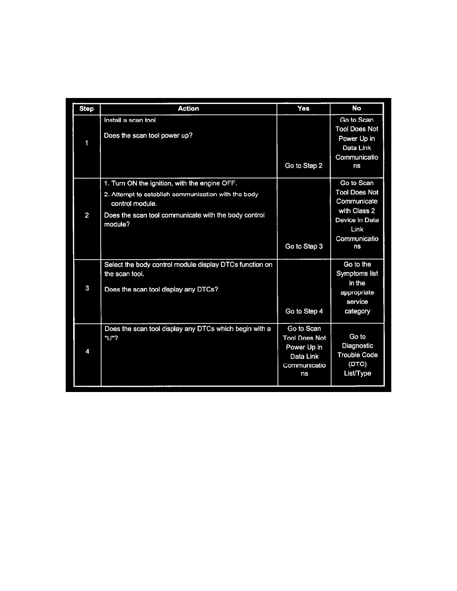
A Diagnostic System Check - Body Control System
Steps 1 - 4
Test Description
The number(s) below refer to the step number(s) on the diagnostic table.
2. Lack of communication may be due to a partial malfunction of the class 2 serial data circuit or due to a total malfunction of the class 2 serial data
circuit. The specified procedure will determine the particular condition.
3. This step is checking for DTCs in the body control module.
4. The presence of DTCs which begin with "U" indicate some other module is not communicating. The specified procedure will compile all the
available information before tests are performed.
Description of On-Board Diagnostics
Diagnostic Information
Use the Diagnostic Trouble Code (DTC) tables. in order to locate a faulty circuit or a component through the process of elimination. The BCM performs
a continual self-diagnosis on certain control functions. A DTC sets when a malfunction is detected by the BCM. The BCM will not turn the SERVICE
ENGINE SOON malfunction indicator lamp (MIL) to the ON position.
Class 2 Serial Data Communication