
Hombre S Space Cab 2WD V6-4.3L (2000)
31. Adjust the electrical BTSI actuator by performing the following steps:
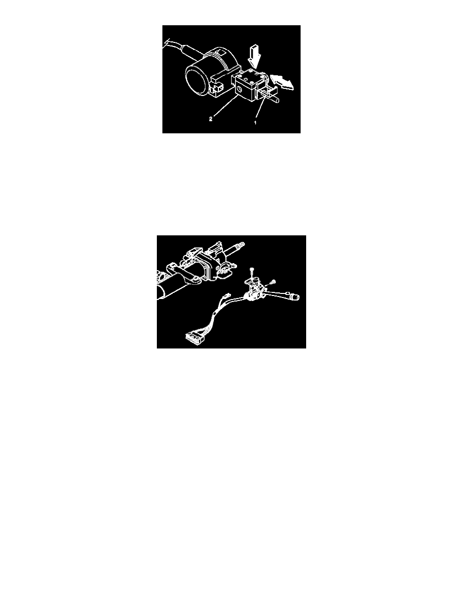
1. Pull out the tab (1) on the adjuster block (2) side of the electrical BTSI actuator.
2. Press on the adjuster block (2) to compress the internal adjuster spring, which disengages the adjuster teeth.
3. Slide the adjuster block (2) as far away from the solenoid as possible.
4. Push inward on the tab (1) in order to lock the adjuster block (2) in place.
32. Inspect the electrical BTSI actuator for the following items:
1. The electrical BTSI actuator must lock the shift lever clevis when the shift lever clevis is put into the park position.
Once the steering column is installed in the vehicle, the gear shift lever must remain in the park position unless the brake pedal is depressed.
2. The solenoid will be energized.
33. Readjust the electrical BTSI actuator if needed.
34. Install the turn signal and multifunction switch assembly onto the steering column tilt head assembly.
Important: Be sure that the electrical contact of the turn signal and multifunction switch assembly (2) rests on the turn signal cancel cam
assembly.
35. Screw the 2 pan head tapping screws into the turn signal and multifunction assembly.
Tighten
Tighten the 2 pan head tapping screws to 7 Nm (62 inch lbs.).
36. Install the tilt spring only.
37. Install the lock module assembly.