
Hombre S Space Cab 2WD V6-4.3L (2000)
Ball Joint: Service and Repair
Upper
Removal Procedure
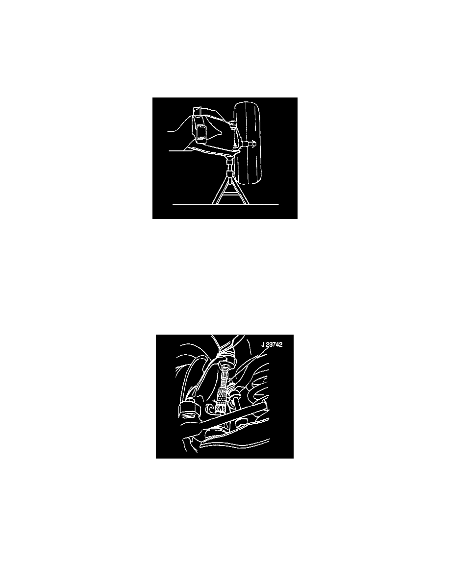
Tools Required
J 23742 Ball Joint Separator
Caution: Floor jack must remain under the lower control arm during removal and installation to retain the lower control arm in position.
Failure to do so could result in personal injury.
1. Raise and suitably support lower control arm with safety stands.
2. Because the weight of the vehicle is used to relieve spring tension on the upper control arm, position the floor stands between the spring seats and
the ball joints of the lower control arms.
3. Remove the tire and wheel assembly.
Notice: Support the caliper with a piece of wire to prevent damage to the brake line.
4. Remove the brake caliper.
5. Remove the cotter pin.
6. Remove wheel speed sensor electrical connector from upper control arm.
7. Disconnect wheel speed sensor electrical connector.
8. Remove the upper ball joint stud nut.
9. Separate the ball joint from the steering knuckle using J 23742.
10. Apply pressure on the tool until the stud breaks loose.
11. Remove J 23742.
12. Pull the ball joint stud away from the steering knuckle.